
Work machine and method of controlling work machine

Active Publication Date: 2020-10-01
KOMATSU LTD
View PDF0 Cites 0 Cited by
  • Summary
  • Abstract
  • Description
  • Claims
  • Application Information

AI Technical Summary

Benefits of technology

The work machine and the method of controlling it can prevent the device from tilting while in use.

Problems solved by technology

An amount of delivery by the hydraulic pump in response to a command current, however, has hysteresis characteristics.
In spite of the same amount of operation of travel control levers, due to the hysteresis characteristics of the hydraulic pump, amounts of delivery of hydraulic oil supplied by the hydraulic pumps to the hydraulic motors may be different between the left and right sides and deflection in travel may occur.

Method used


Image

  • Work machine and method of controlling work machine
  • Work machine and method of controlling work machine
  • Work machine and method of controlling work machine

Examples


Embodiment Construction

[0019]An embodiment of the present invention will be described below with reference to the drawings. The same elements in the description below have the same reference characters allotted and their labels and functions are also the same. Therefore, detailed description thereof will not be repeated. In the description below, terms “up”, “down”, “front”, “rear”, “left”, and “right” are used with an operator seated at an operator's seat being defined as the reference.

[0020]

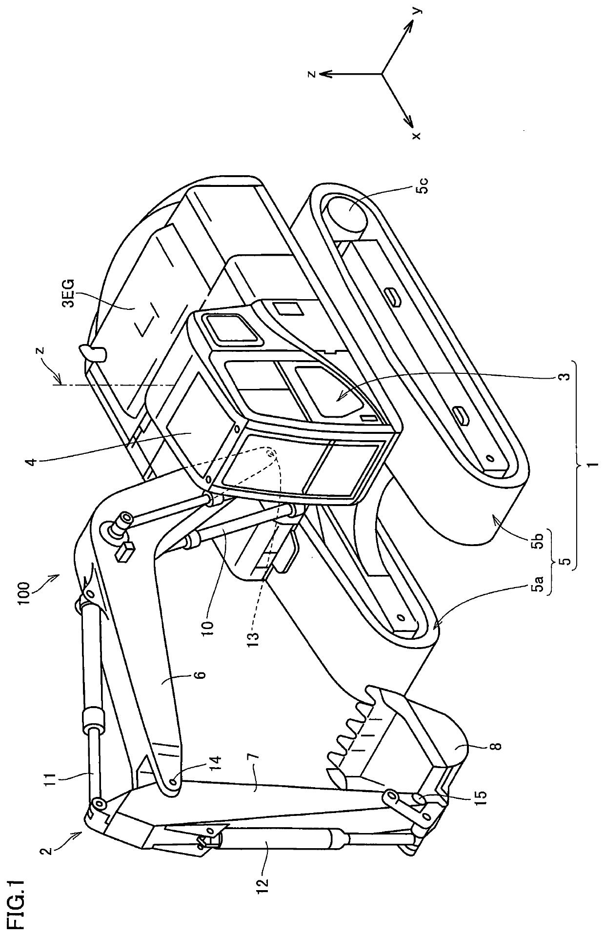
[0021]FIG. 1 is a perspective view of a work machine based on an embodiment.

[0022]As shown in FIG. 1, a hydraulic excavator 100 representing a work machine includes a vehicular main body 1 and a work implement 2.

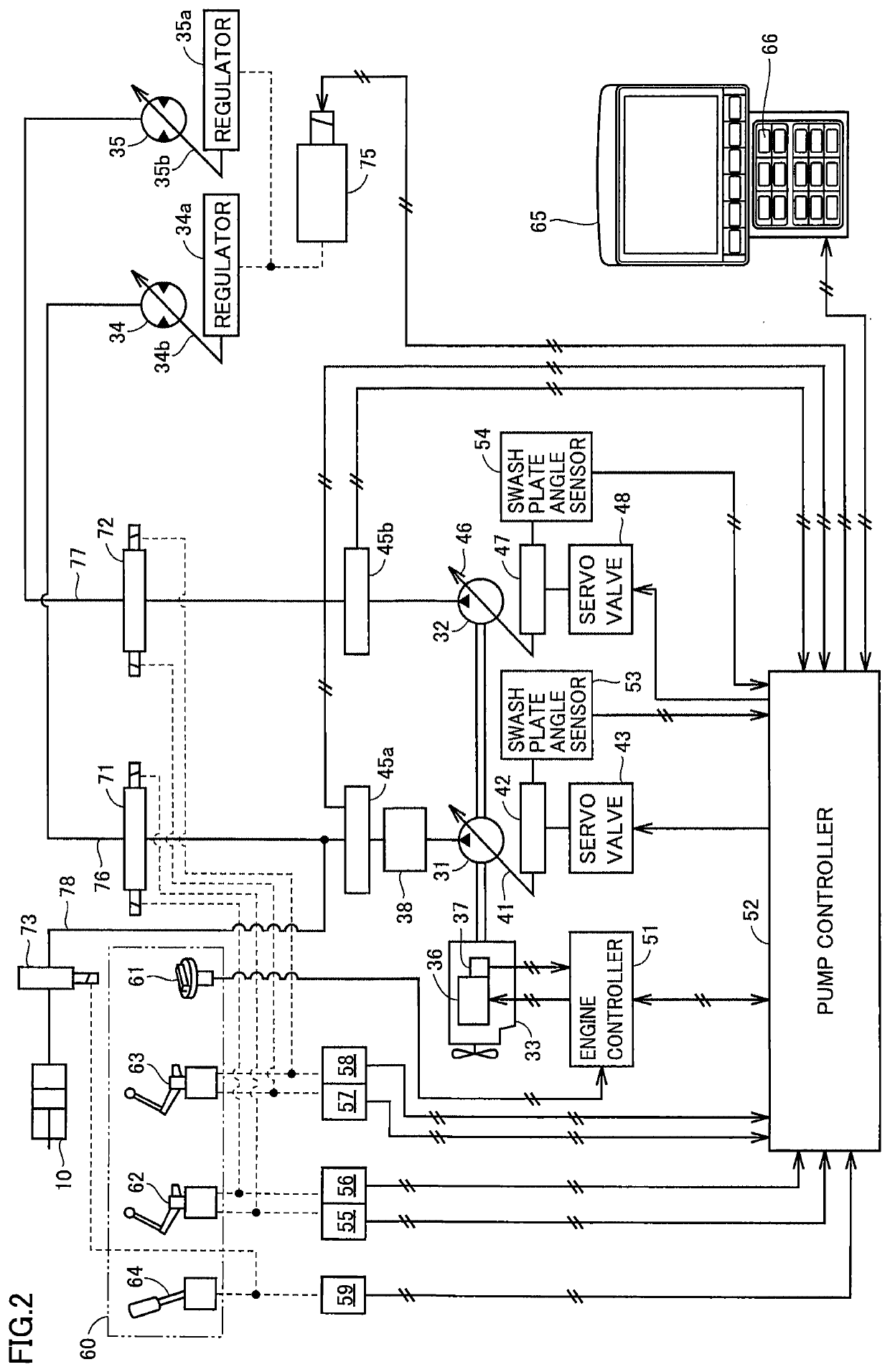
[0023]Vehicular main body 1 includes an upper revolving unit 3 representing a revolving unit and a traveling apparatus 5 as a travel unit. Upper revolving unit 3 accommodates an apparatus such as an internal combustion engine as a power generator and a hydraulic pump in an engine compartment 3EG. Engine compa...


PUM


Abstract

A work machine includes first and second hydraulic motors, first and second hydraulic pumps provided to supply hydraulic oil in correspondence with the first and second hydraulic motors, respectively, first and second swash plate angle sensors provided in correspondence with swash plates which regulate amounts of delivery by the first and second hydraulic pumps, respectively, the first and second swash plate angle sensors each detecting an angle of the swash plate, a delivery amount setting unit which sets an ideal amount of delivery by the first and second hydraulic pumps, and a command value control unit which corrects a command value for adjusting an angle of the swash plate such that the amount of delivery in accordance with a result of detection by the first and second swash plate angle sensors is set to the ideal amount of delivery.

Description

TECHNICAL FIELD[0001]The present invention relates to a work machine including a hydraulic pump and a method of controlling a work machine.BACKGROUND ART[0002]A work vehicle includes a hydraulic pump and a hydraulic motor and runs as the hydraulic motor is driven with hydraulic oil delivered from the hydraulic pump. A variable displacement hydraulic pump which can vary an amount of delivery with change in position of the swash plate is employed as the hydraulic pump.[0003]In the work vehicle, a position of the swash plate is controlled by sensing with a hydraulic sensor, a control hydraulic pressure of a regulator which moves the swash plate or by sensing a command current to a proportional solenoid valve which controls a control hydraulic pressure (see PTLs 1 and 2).[0004]An operator operates two travel control levers to drive hydraulic motors mounted on left and right traveling apparatuses, respectively. In an example in which hydraulic oil is supplied by different hydraulic pumps...

Claims


Application Information

Patent Timeline
IPC IPC(8): B60K6/22E02F9/22E02F9/20F04B1/29F04B49/06F15B11/02
CPCE02F3/32F15B11/02E02F9/2296F04B49/06E02F9/2292E02F9/2004E02F9/2285E02F9/2235F04B1/29B60K6/20B60Y2200/412F16H2059/6846F16H61/431F16H61/44
Inventor OHIGASHI, KOJI
Owner KOMATSU LTD
Learn More