Drive mechanism of two degrees of freedom

Active Publication Date: 2019-06-06
KAWASAKI HEAVY IND LTD
View PDF0 Cites 4 Cited by
  • Summary
  • Abstract
  • Description
  • Claims
  • Application Information

AI Technical Summary

Benefits of technology

The present invention provides a drive mechanism that allows a mounted structure to operate in a compact way with a desired angle range of two degrees of freedom. This mechanism also suppresses deflection of the structure.

Problems solved by technology

However, when trying to ensure the large operation angle range in the joint portion at two degrees of freedom, particularly a deflection in the pitch direction increases and a large gear is needed to ensure a required joint torque.

Method used


Image

  • Drive mechanism of two degrees of freedom
  • Drive mechanism of two degrees of freedom
  • Drive mechanism of two degrees of freedom

Examples


Embodiment Construction

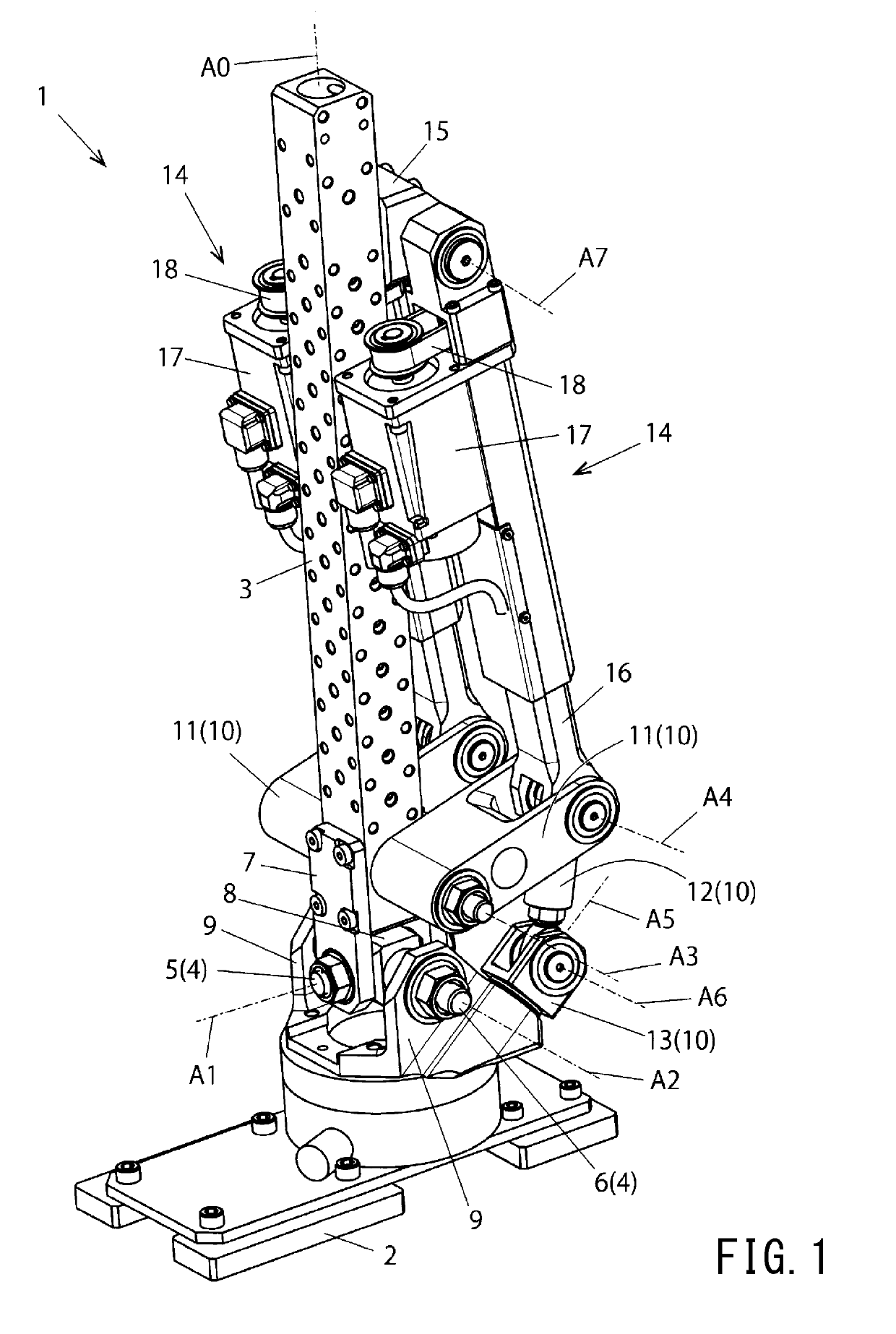
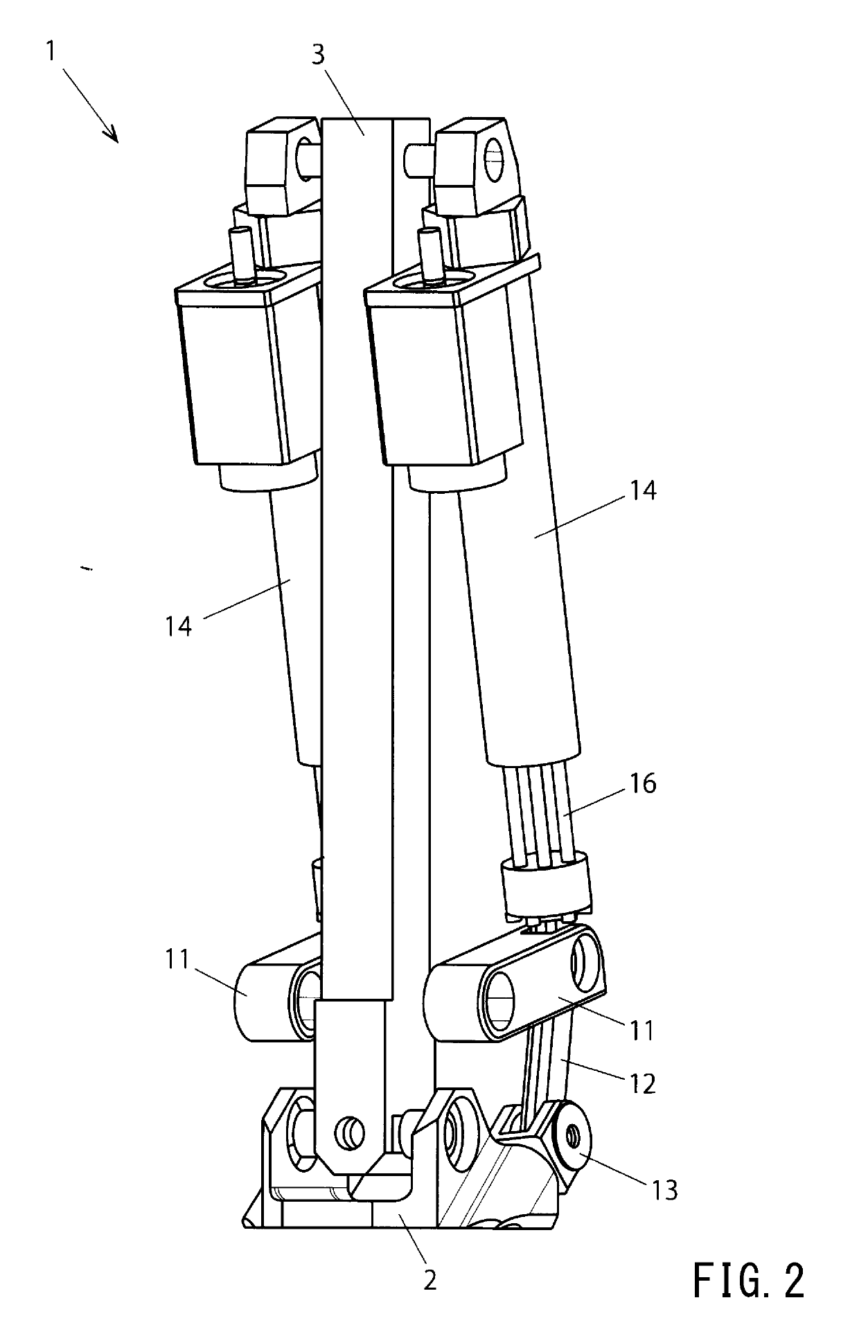
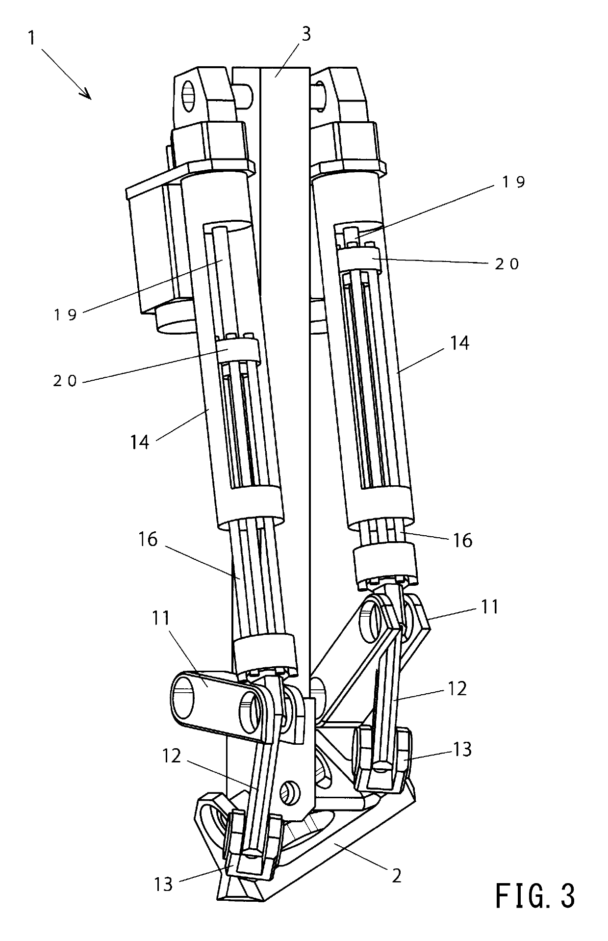
[0026]Hereunder, a drive mechanism according to one embodiment of the present invention will be described referring to the drawings. Note that the drive mechanism according to this embodiment is particularly suitable for a drive mechanism in a joint portion (for example, ankle joint) of a humanoid robot.

[0027]Note that the drive mechanism according to the present invention is not limited to application to the joint portion of the humanoid robot and can be broadly applied to a drive mechanism in a driven body requiring operation of at least two degrees of freedom.

[0028]The drive mechanism 1 according to this embodiment illustrated in FIG. 1 is for realizing the operation of two degrees of freedom in a driven body 2. The driven body 2 is for example a component of an ankle joint of the humanoid robot, and performs operation of at least two degrees of freedom upon walking.

[0029]The drive mechanism 1 comprises an elongated frame member (base portion) 3 having a center axis A0 in the lon...


PUM


Abstract

A power transmission unit of a drive mechanism has a link mechanism on both sides of a base portion. The link mechanism has a first link member having a base end portion provided to the base portion to be rotated about a third rotational axis, a second link member having a base end portion connecting the first link member's distal end portion to be rotated about a fourth rotational axis, and a third link member which is provided to a driven body to be rotated about a fifth rotational axis and to which the second link member's distal end portion is provided to be rotated about a sixth rotational axis orthogonal to the fifth rotational axis. A desired operation angle range of two degrees of freedom in a driven body can be ensured with a compact configuration while suppressing deflection of a structure to which the driven body is mounted.

Description

TECHNICAL FIELD[0001]The present invention relates to a drive mechanism for transmitting power to a driven body to drive the same with operation of two degrees of freedom, and particularly to a drive mechanism applicable to a joint structure of a robot.BACKGROUND ART[0002]Conventionally, in a robot having a joint structure, various drive mechanisms are adopted for operating a joint portion in a desired angle range.[0003]For example, in a humanoid robot, a drive mechanism for operating a joint portion such as an ankle joint is provided. Here, the joint portion of the humanoid robot needs to realize both a tilt operation about a rotational axis extending in the cross direction (roll operation) and a tilt operation about a rotational axis extending in the lateral direction (pitch operation).[0004]Additionally, in order to realize bipedal walking of the robot, it is needed to move the joint portion in a relatively large angle range. To realize this, a planetary gear speed increasing mec...

Claims


Application Information

Patent Timeline
IPC IPC(8): B25J17/02
CPCB25J17/0275B25J17/0266B25J17/00F16H21/02F16H21/46B25J9/106B25J9/123B62D57/032F16C11/06
Inventor KAMON, MASAYUKI
Owner KAWASAKI HEAVY IND LTD
Why Eureka
Try Eureka