Acceleration sensor core unit, and method for preventing deflection of a base board on which acceleration sensor is mounted

Active Publication Date: 2022-04-19
IMV
View PDF21 Cites 0 Cited by
  • Summary
  • Abstract
  • Description
  • Claims
  • Application Information

AI Technical Summary

Benefits of technology

The patent text is about a new technology that prevents the base board from bending and accurately detects acceleration. This helps to improve the performance of the technology.

Problems solved by technology

However, it is understood that, when the inventor conducted an experiment, the core unit 112 illustrated in FIG. 1 could not demonstrate detection accuracy of the small-sized sensor itself.

Method used


Image

  • Acceleration sensor core unit, and method for preventing deflection of a base board on which acceleration sensor is mounted
  • Acceleration sensor core unit, and method for preventing deflection of a base board on which acceleration sensor is mounted
  • Acceleration sensor core unit, and method for preventing deflection of a base board on which acceleration sensor is mounted

Examples


Embodiment Construction

[0018]A description will be made on an embodiment of the present invention with reference to the drawings.

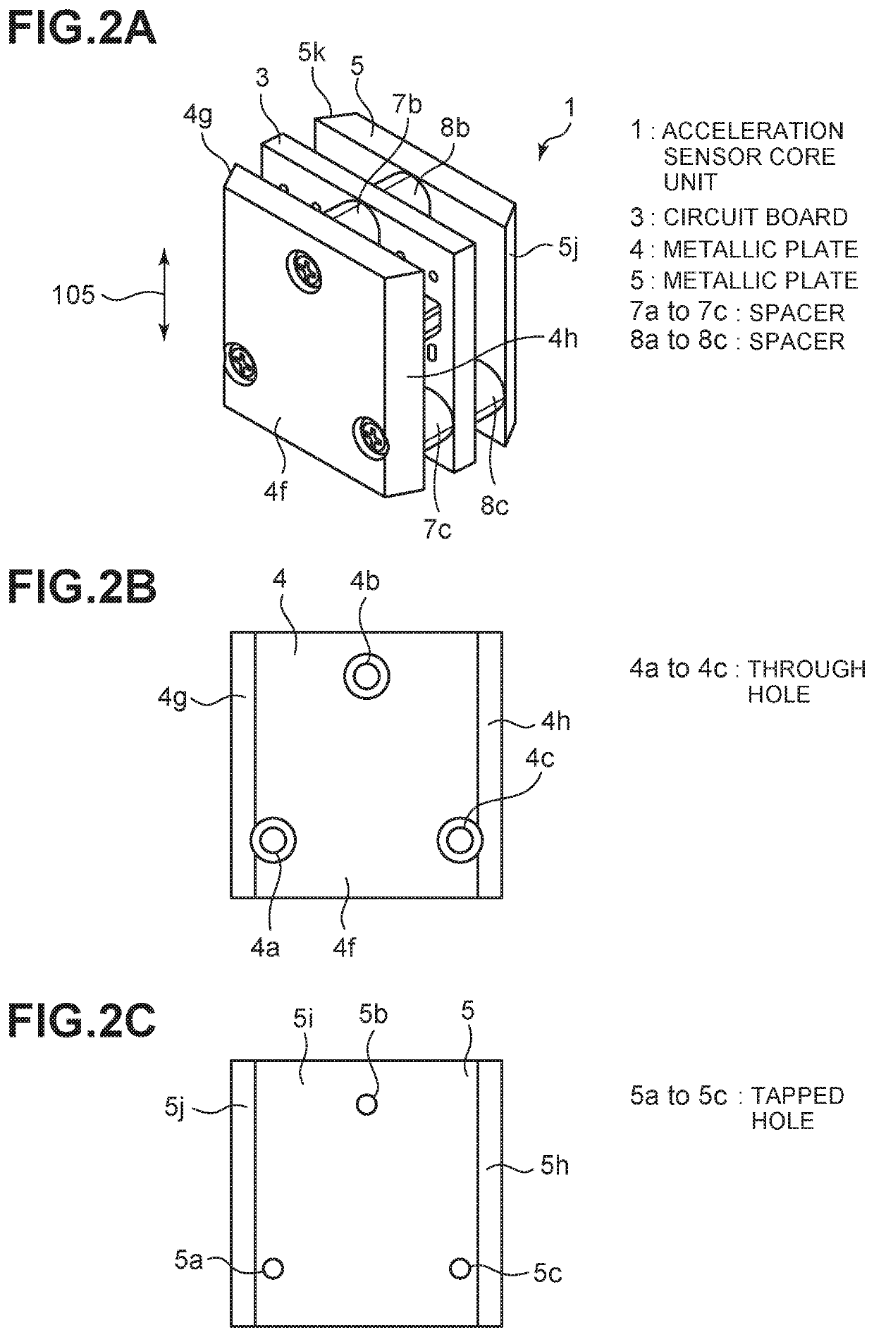
[0019]FIG. 2A illustrates an acceleration sensor core unit 1 according to the embodiment of the present invention. The acceleration sensor core unit 1 includes a circuit board 3 as a base board, a metallic plates 4, 5, and spacers 7a to 7c, 8a to 8c.

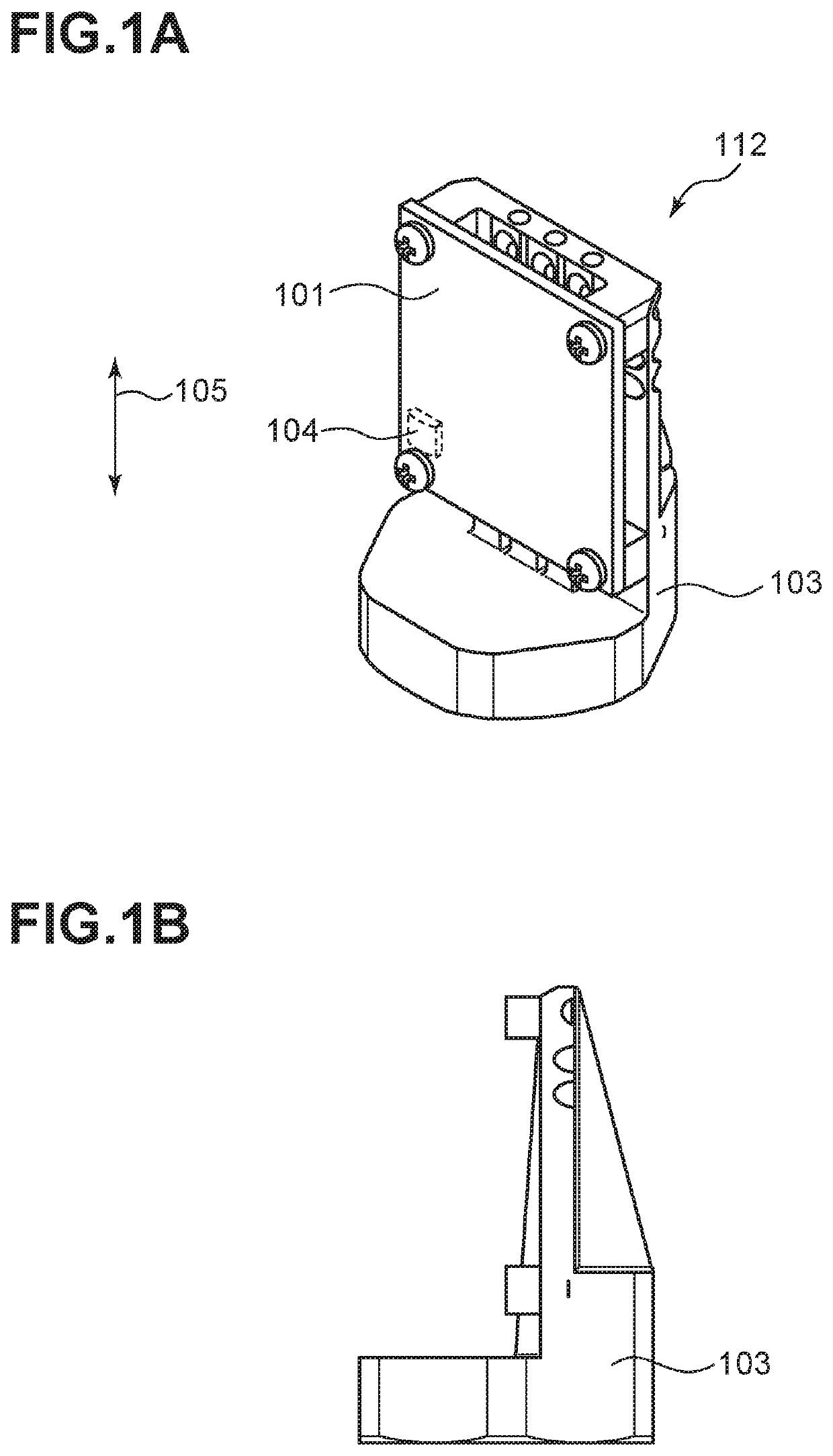
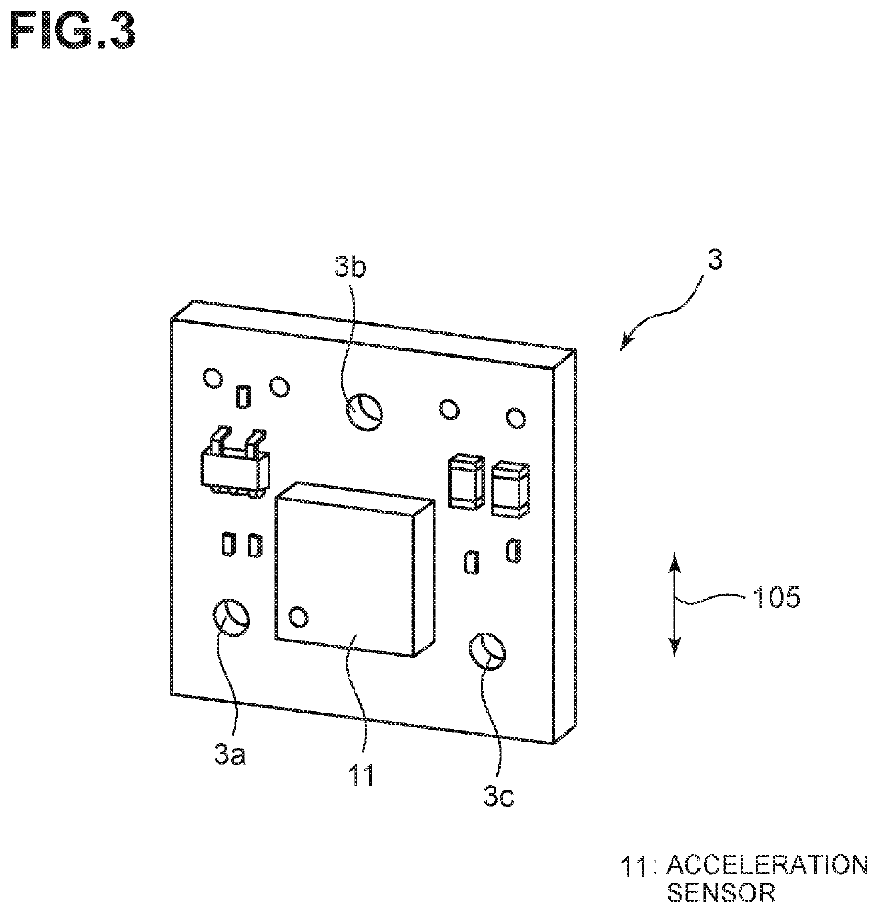
[0020]The circuit board 3 is made of a glass epoxy resin, and as illustrated in FIG. 3, an acceleration sensor 11 and various electronic components are mounted on a surface thereon. In addition, through holes 3a to 3c are provided at three positions. The acceleration sensor 11 detects vibration acceleration in an arrow 105 direction.

[0021]As illustrated in FIG. 2A, the circuit board 3 is sandwiched between the metallic plates 4, 5. The metallic plates 4, 5 are illustrated in FIGS. 2B and 2C, respectively. As illustrated in FIG. 2B, the metallic plate 4 is provided with through holes 4a to 4c subjected to counter boring. As illustrat...


PUM


Abstract

An acceleration sensor core unit 1 includes a circuit board 3 and metallic plates 4, 5. The circuit board 3 is made of an epoxy resin, and an acceleration sensor 11 for detecting vibration acceleration in an arrow 105 direction is mounted thereon. The circuit board 3 is sandwiched between the metallic plates 4, 5. Ring-shaped metallic spacers 7a to 7c and ring-shaped metallic spacers 8a to 8c are respectively interposed between the circuit board 3 and the metallic plate 4 and between the circuit board 3 and the metallic plate 5. The circuit board 3 is screwed to each of the metallic plates 4, 5 at three positions. Thus, it is possible to reliably fix the circuit board 3 to the metallic plates 4, 5 with a small attachment space. In this way, rigidity as the acceleration sensor core unit 1 can be secured.

Description

CROSS REFERENCE TO RELATED APPLICATIONS[0001]This application claims the benefit under 35 U.S.C. 119(a) to Japanese Patent Application No. JP 2019-095640, filed May 22, 2019, the entire disclosure of which is incorporated herein by reference in its entirety.TECHNICAL FIELD[0002]The present invention relates to an acceleration sensor and, in particular, to prevention of deflection of a base board on which an acceleration sensor is mounted.BACKGROUND ART[0003]Patent Document 1 (WO 2015 / 145489) discloses a sensor unit, in which an acceleration sensor (hereinafter referred to as a MEMS acceleration sensor) manufactured in a MEMS process (semiconductor microfabrication) is stored in a casing. The sensor unit is a three-axis acceleration sensor.[0004]As such a MEMS acceleration sensor, a small-sized acceleration sensor specialized in detecting acceleration in one axis direction has been known. The inventor has invented a core unit, in which this small-sized acceleration sensor is mounted ...

Claims


Application Information

Patent Timeline
IPC IPC(8): G01P15/08G01P1/02G01P15/18
CPCG01P15/08G01P1/02G01P1/023G01P15/18G01P15/02
Inventor KOBAYASHI, TOSHIYUKIKAWAHIRA, TAKAO
Owner IMV
Why Eureka
Try Eureka