Navigational interface for mobile and wearable computers

a navigation interface and wearable technology, applied in the field of user interfaces, can solve problems such as implementation, and achieve the effect of convenient use and fastness

Inactive Publication Date: 2005-03-03
SZ DJI TECH CO LTD
View PDF17 Cites 66 Cited by
  • Summary
  • Abstract
  • Description
  • Claims
  • Application Information

AI Technical Summary

Benefits of technology

[0015] The great utility of the invention is that users may interact with a computing system through a navigational interface using only one input device. The advantages of this utility become even more apparent as consumers demand smaller, faster, and easier to use computers. In particular, this invention will be of great importance to designers of personal digital assistants, handheld personal computers, mobile computers, and wearable computers. Not only does the present invention allow users to operate such devices using one hand, but it also provides for interaction while on the move.
[0016] Another great utility of the invention is that the navigational interface can be used as either a navigational interface within a graphical user interface (GUI), such as Windows® CE, or as the only user interface on the computing system. The navigational interface is designed to lead to muscle memory, thereby allowing a user to navigate through applications and input text without looking at the navigational interface navigational display.

Problems solved by technology

However, this implementation had its disadvantages because, by design, the user's hands and the light pen would obscure a portion of the screen from the user's own view.
This and other disadvantages led to the development of the mouse, an interface control separate from the keyboard, that controlled a pointer on the GUI for selecting and highlighting objects, buttons, and windows.
The growth of the personal digital assistant (“PDA”) and wearable computer markets are associated with similar problems realized in the larger-scale computing systems.
While such interaction is similar to the use of a conventional pad and paper, it is not without problems.
Further, the stylus-based GUI requires two-hand operation and typically requires the user to look at the device while using it.

Method used


Image

  • Navigational interface for mobile and wearable computers
  • Navigational interface for mobile and wearable computers
  • Navigational interface for mobile and wearable computers

Examples


Embodiment Construction

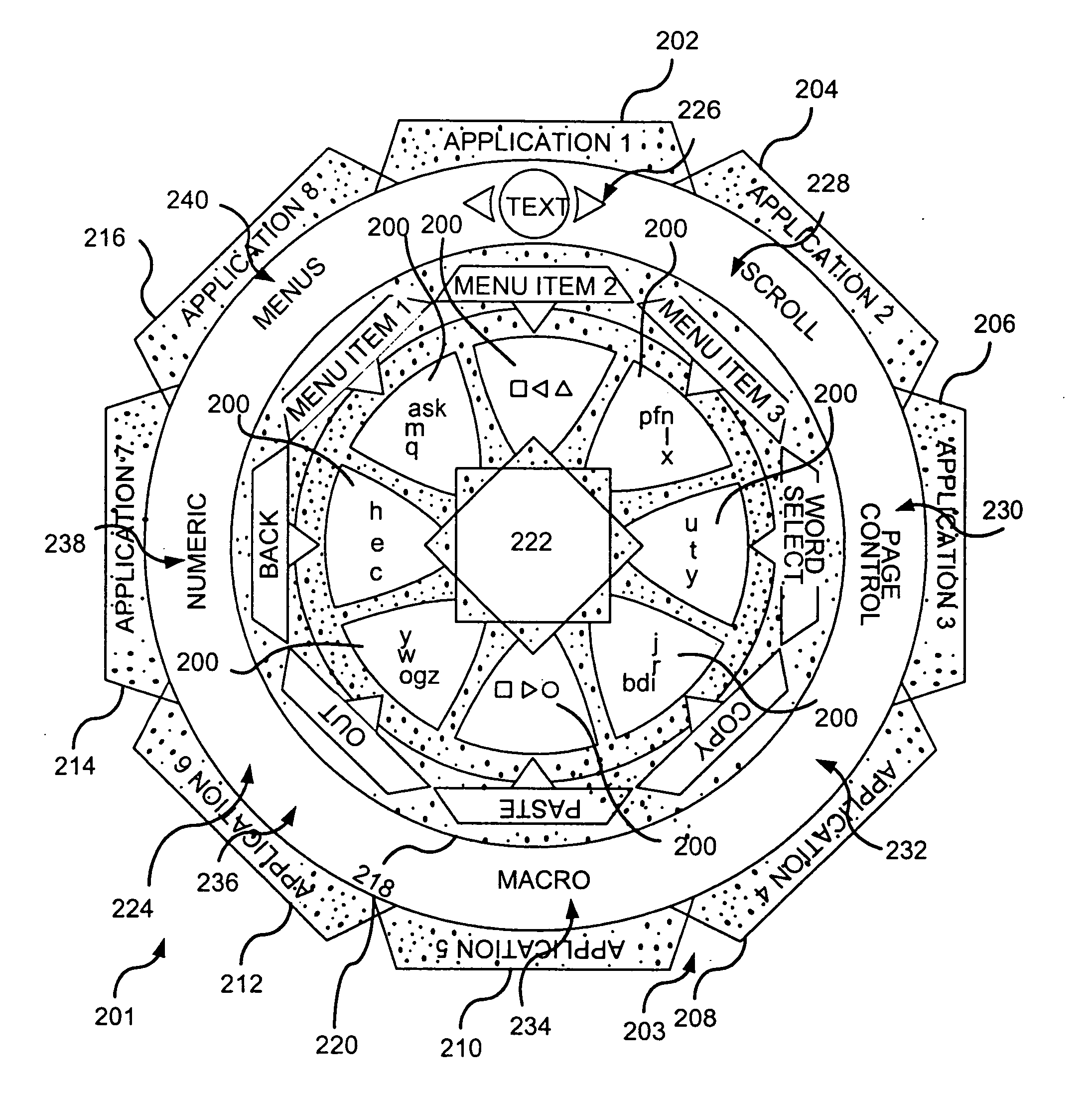
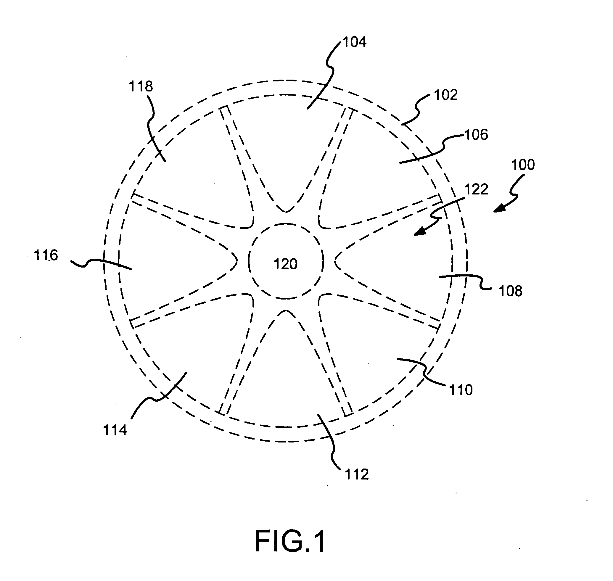
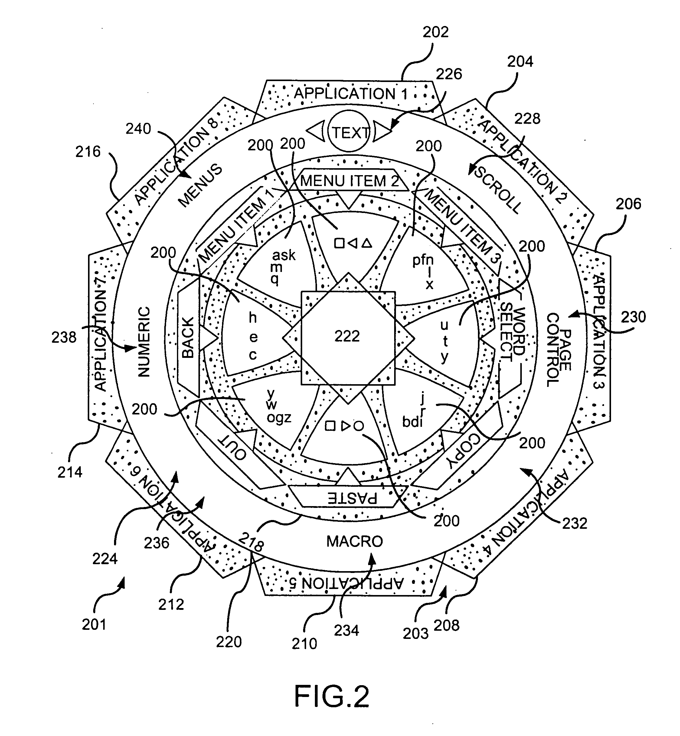
[0028]FIG. 1 is a conceptual illustration of a sensor pattern 100 of a navigational interface in accordance with an embodiment of the present invention. The sensor pattern 100 is divided into a predetermined array of graphical fields 102-120, or portions. The sensor pattern 100 is radially divided into a central sensory portion 120, a petals sensory portion 122 divided into sensory petals 104-118, and an outer sensory, or circumferential, portion 102. In accordance with an embodiment of the present invention, the circumferential portion 102 is located on the outermost edge of the sensor pattern 100. The petals sensory portion 122 is angularly divided into a predetermined number of graphical sensory petals 104-118. In one embodiment, the sensor pattern 100 contains eight sensory petals 104-118. In other embodiments, the sensor pattern 100 might contain any number of sensory petals 104-118. In accordance with an embodiment, the central sensory portion 120 and the circumferential porti...


PUM


Abstract

The navigational interface allows a user to control computer operations and input text into applications running on the computing system with a single input device. The navigational interface operates by receiving selection signals from the input device. The navigational interface includes an input device, a navigational interface interpretation module having a sensor pattern, and a control display providing feedback of the navigational interface interpretation module operations. The sensor pattern is radially divided into a central sensory portion, a petals sensory portion divided into sensory petals, and a circumferential sensory portion. Each sensory portion references an information element. The information elements are associated with tasks to be performed in the computing system. The tasks might be computer control operations, application selection, application operation, or inputting and editing of textual characters into various applications running on the computing system. The information elements are selected by a selection stroke on the sensory portions and sensory petals of the sensor pattern. The selection stroke is defined by information in the selection signal, which is transmitted pursuant to a user input stroke. Tasks are performed through recognization of the selection signal by the navigational interface interpretation module. Following task execution, the information elements associated with the sensor pattern are functionally updated according to the executed task.

Description

TECHNICAL FIELD [0001] The invention relates generally to a user interface providing interaction between a user and a computing system. More particularly, the invention relates to a navigational interface for control operation and textual input into a computer. BACKGROUND OF THE INVENTION [0002] As computers have become more complex, user interfaces have had to adapt to allow the user to control the operations of the computer. Initially, the interface- used was a command line interface, which utilized a series of typed commands formatted in a specific syntax familiar to the computer and eventually learned by computer users. This interface was eventually replaced by the Graphical User Interface (“GUI”), which allows users to point to objects, buttons, and windows displayed like items on a desk. Initially, interaction between the GUI and a user was accomplished through a light pen, a pen-based computer control requiring the user to select and highlight objects on the screen by touchin...

Claims


Application Information

Patent Timeline
Patent Type & Authority Applications(United States)
IPC IPC(8): G06F3/023G06F3/033G06F3/048
CPCG06F3/0233G06F3/04883G06F3/03547
Inventor SANGIOVANNI, JOHN
Owner SZ DJI TECH CO LTD
Why Eureka
Try Eureka