Utility tool handle

a technology of utility tools and handles, applied in the field of ergonomic handles, can solve the problems of not properly applying prior art to this new tool and implement, and achieve the effects of undue strain, reducing strain and repetitive motion injuries, and reducing fatigue and repetitive motion injuries

Inactive Publication Date: 2005-03-10
BIGGS BLYTH S
View PDF8 Cites 18 Cited by
  • Summary
  • Abstract
  • Description
  • Claims
  • Application Information

AI Technical Summary

Benefits of technology

[0013] After considerable work on rakes of various types, I once again turned to the ergonomic principles involved and have now developed a a utility tool handle which works with rakes of all types and numerous other domestic tools. I have now finally perfected the present invention of a unique and very useful ergonomic utlity tool handle. It is now possible, as a result of my present invention, to reduce the fatigue and repetitive motion injuries and the undue strain previously encountered by persons involved with raking and hoeing and numerous other activities.
[0014] It is an object of this invention to provide a new, useful, and unique utility tool handle which will relieve strain and repetitive motion injuries for persons using utility tools;
[0015] Another object of this invention is to provide such a handle which is useful in making the use of utility tools more effective;
[0016] Another object of this invention is to provide such a utility tool handle which can be utilized equally effectively by right or left handed persons.

Problems solved by technology

I have concluded that there is no properly applicable prior art as to this new tool and implement.

Method used


Image

  • Utility tool handle
  • Utility tool handle

Examples


Embodiment Construction

[0020] An inventory of items on the drawings bearing reference numerals is:

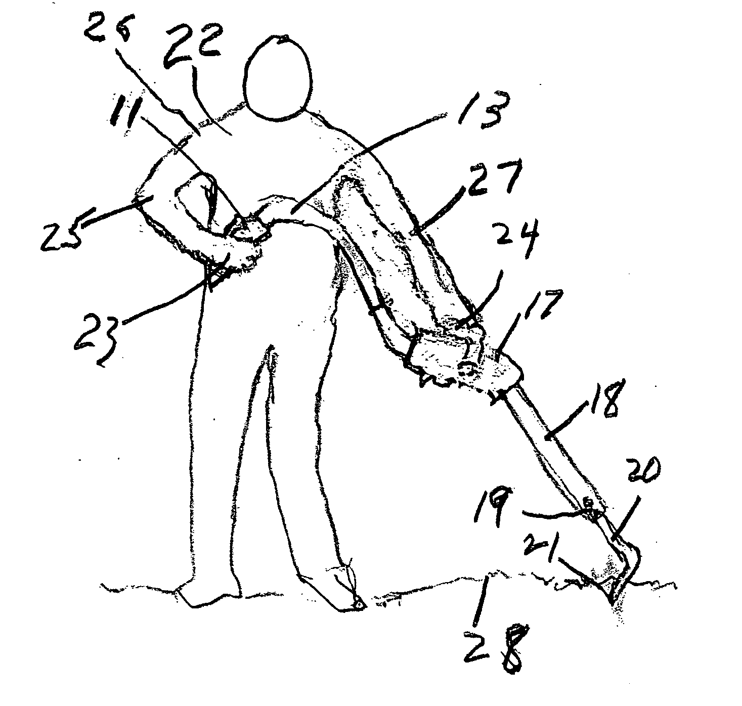
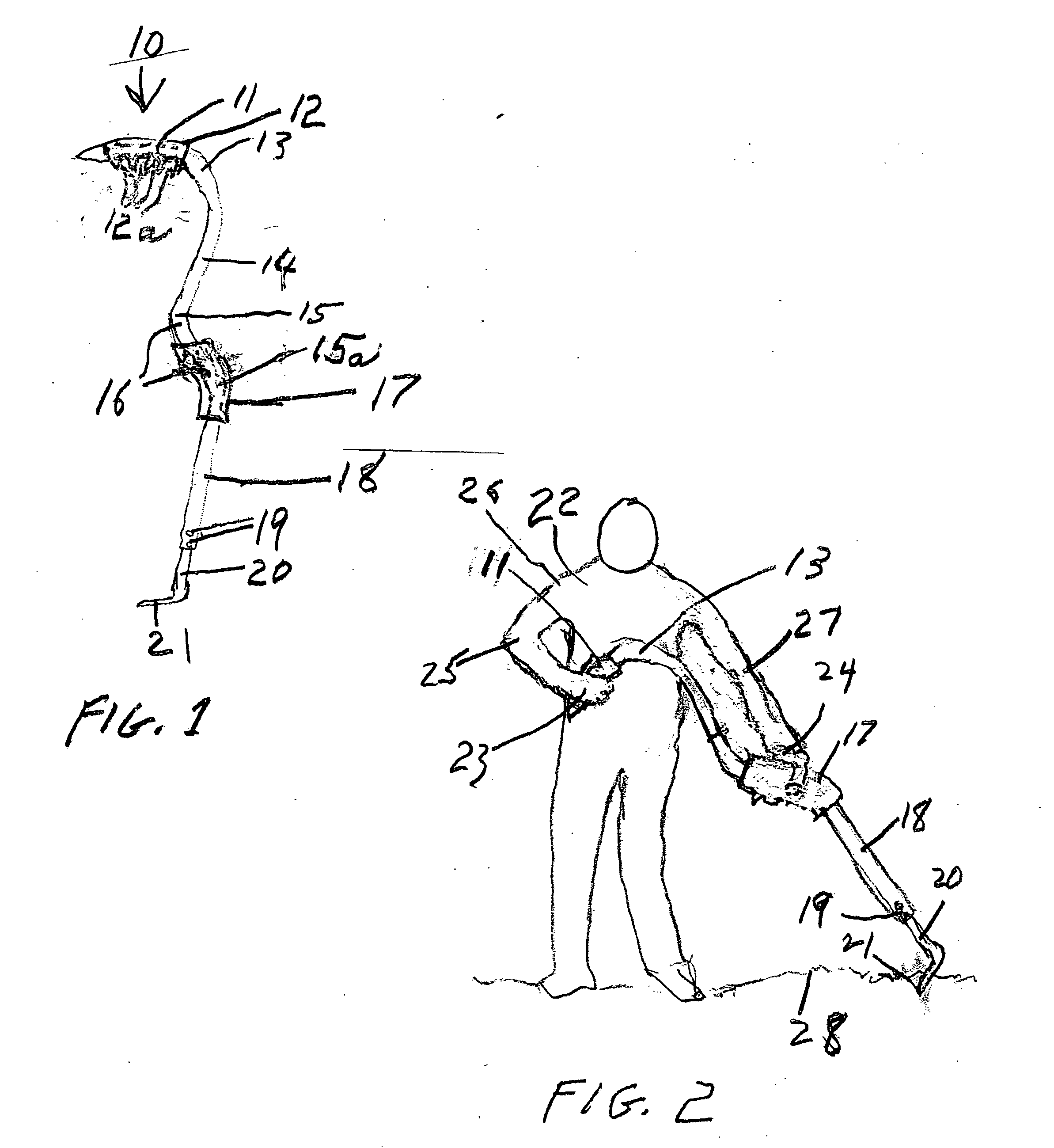
NumeralItem10ergonomic utility tool handle, generally11straight segment of handle in phantom12end covering12afinger-holds13curved segment14straight segment15curved segment15acurved segment16straight segment partially in phantom17hand grip covering18straight segment19fasteners20tool attachment member21hoe blade22person23right hand24left hand25right arm26right shoulder27left arm28ground surface

[0021] The new utility tool handle 10 of this invention is shown in FIG. 1. It consists of rod or pipe specially shaped as shown and described. I prefer a hollow cylindrical tube of aluminum although any suitable elongate member would do as will be clear to those skilled in the art.

[0022] The tube or the like is shaped as follows: an initial straight segment 11 is about four inches in length. The segment 11 has a shaped covering 12 having a series of finger-holds 12a on its underside.

[0023] A curved segment 13 approxi...


PUM


Abstract

This is a utility tool handle comprising an elongate handle which is especially designed with four straight segments and three curved segments with special hand holds so that a work-person or the like can exert maximum pulling power with a first hand while exerting maximum downward pressure with a second hand.

Description

CROSS REFERENCE TO RELATED PATENT APPLICATIONS [0001] This application is not related to any other presently pending application of mine. BACKGROUND OF THE INVENTION [0002] I. FIELD OF THE INVENTION [0003] This invention is in the general field of utility hand tools such as rakes, hoes, shovels, brooms, mops, and the like; [0004] The invention is more particularly in the field of ergonomic handles for utility hand tools having elongate handles. [0005] II. DESCRIPTION OF THE PRIOR ART [0006] For many years I have been personally engaged in such activities as janitorial work, gardening, soil preparation, and the like. In my work I have used tools and implements such as rakes, hoes, shovels, brooms, mops, and the like. I am familiar with the many different types of handles for such items. Over a long period of time I have sought for the most ergonomic friendly handles for such implements and tools. [0007] I co-invented the ergonomic mop handle illustrated in U.S. Pat. No. 5,920,944. I ...

Claims


Application Information

Patent Timeline
Patent Type & Authority Applications(United States)
IPC IPC(8): A01B1/00A01D7/00A45B9/02B25G1/10
CPCA01B1/00A01D7/00Y10T16/476B25G1/102A45B9/02
Inventor BIGGS, BLYTH S.
Owner BIGGS BLYTH S
Why Eureka
Try Eureka