Method for controlling flow rate of ventilating air in air conditioner

a technology of air conditioner and flow rate, which is applied in the field of air conditioner, can solve the problems of long time period and gradual polluting of air in such a closed room

Inactive Publication Date: 2005-03-10
LG ELECTRONICS INC
View PDF1 Cites 6 Cited by
  • Summary
  • Abstract
  • Description
  • Claims
  • Application Information

AI Technical Summary

Benefits of technology

[0013] An object of the present invention is to provide a method for controlling a flow rate of ventilating air in an air conditioner, in which the room can be ventilated, quickly.
[0014] Other object of the present invention is to provide a method for controlling a flow rate of ventilating air in an air conditioner, in which heat can be recovered from room air discharged to an outside of a room in a process of ventilation.
[0015] Another object of the present invention is to provide a method for controlling a flow rate of ventilating air in an air conditioner, in which the room can be cooled / heated continuously even if the room is ventilated.

Problems solved by technology

Air in such a closed room is polluted gradually as time passes by.
In a ventilating process, there is even a problem in that the outdoor air introduced into the room is discharged to the outside of the room directly through a discharge duct before the outdoor air replaces the room air, adequately.
Consequently, for complete ventilation of the room, a long time period is required.

Method used


Image

  • Method for controlling flow rate of ventilating air in air conditioner
  • Method for controlling flow rate of ventilating air in air conditioner
  • Method for controlling flow rate of ventilating air in air conditioner

Examples


Embodiment Construction

[0030] Reference will now be made in detail to the preferred embodiments of the present invention, examples of which are illustrated in the accompanying drawings. In describing the embodiments of the present invention, same parts will be given the same names and reference symbols, and repetitive description of which will be omitted.

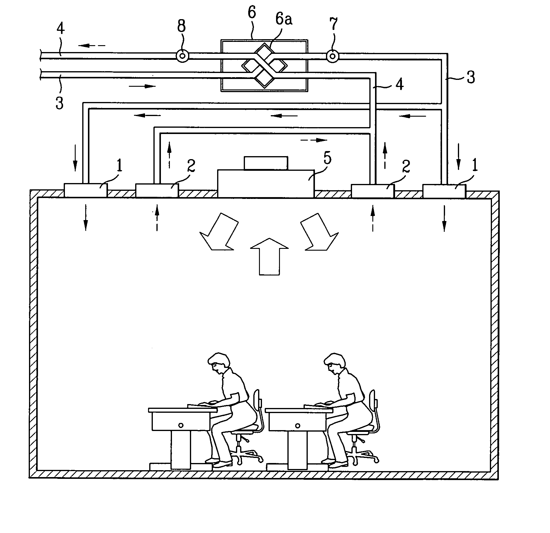
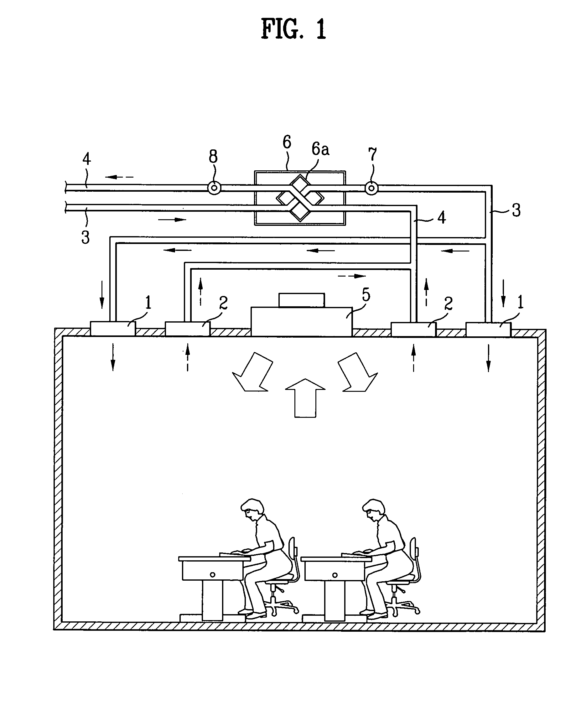
[0031] The air conditioning system of the present invention provides a ceiling type air conditioner of which indoor unit is installed on a ceiling. The air conditioning system of the present invention can ventilate a room, in which air supplied to the room recovers heat from air discharged to an outside of the room. FIG. 1 illustrates a diagram of an air conditioner in accordance with a preferred embodiment of the present invention, schematically, FIG. 2 illustrates a look up view of a ceiling having an air conditioner installed thereon.

[0032] Referring to FIG. 1, there is an indoor unit 5 installed on one point of a ceiling of a room in communication w...


PUM


Abstract

The present invention relates to a method for controlling flow rates of outdoor air supplied to a room and room air discharged to an outside of the room in ventilation. The method of the present invention includes the steps of supplying outdoor air drawn through an air supply duct to a room at a first flow rate, and discharging room air drawn through an air discharge duct to an outside of the room at a second flow rate higher than the first flow rate. The first and second flow rates vary with rotation speeds of fans respectively mounted on an air supply duct and an air discharge duct.

Description

[0001] This application claims the benefit of the Korean Application No. P2003-62624 filed on Sep. 8, 2003, which is hereby incorporated by reference. BACKGROUND OF THE INVENTION [0002] 1. Field of the Invention [0003] The present invention relates to air conditioners, and more particularly, to a method for controlling flow rates of outdoor air supplied to a room and room air discharged to an outside of the room for ventilation for an air conditioner having a ventilating function. [0004] 2. Background of the Related Art [0005] The air conditioner is an appliance for cooling or heating a room by using a property of refrigerant in which the refrigerant discharges or absorbs heat to / from an environment when the refrigerant undergoes a phase change. [0006] In general, the air conditioner is provided with an indoor unit and an outdoor unit, wherein the air conditioner having the indoor unit and the outdoor unit combined into one unit is called as a unit type air conditioner, and the air ...

Claims


Application Information

Patent Timeline
Patent Type & Authority Applications(United States)
IPC IPC(8): F24F1/0038F24F7/10F24F1/0047F24F1/0063F24F1/0067F24F1/0071F24F7/08F24F11/00F24F11/02F24F11/04F24F12/00F24F13/06F24F13/32
CPCF24F1/0007F24F11/0001F24F11/0079F24F11/04Y02B30/563F24F2001/0037F24F2001/0051F24F2013/0616Y02B30/746F24F12/006F24F2012/008F24F11/77F24F11/74F24F1/0047F24F1/0035Y02B30/56Y02B30/70F24F1/0038F24F1/0067F24F1/0063F24F1/0071F24F11/755F24F7/10
Inventor LEE, GI SEOPYUM, KWAN HOKIM, KYUNG HWANKIM, JEONG YONGCHOI, HO SEON
Owner LG ELECTRONICS INC
Why Eureka
Try Eureka