Multicomponent cartridge

a multi-component, cartridge technology, applied in the direction of liquid transfer devices, transportation and packaging, tray containers, etc., can solve the problems of component leakage, no longer guaranteed sealing effect, active sealing of the edge and end-side, etc., to achieve high surface pressure, high sealing effect, and high sealing pressure

Active Publication Date: 2005-03-10
SULZER CHEMTECH AG
View PDF11 Cites 20 Cited by
  • Summary
  • Abstract
  • Description
  • Claims
  • Application Information

AI Technical Summary

Benefits of technology

[0009] The seal of the cartridge according to the invention is realized between the cap and the coaxial outlet by means of circular, lateral sealing edges. These are formed on the outlet tubes of the coaxial outlet and / or on the seal flanges or sealing elements of the cap. The seal is thus realized across a precisely defined and limited contact surface, so that a high surface pressure is produced on a small surface and therefore a higher sealing pressure is enabled. Because the seal acts laterally, excess tightening of the cap in the case of a screw cap is not necessary. Because the sealing edges lead to lateral contact at the corresponding counter-surfaces, a high sealing effect is also achieved without a great axial tightening force. If the cap is configured, e.g., as a screw cap, the seal itself then remains guaranteed when the cap is not completely screwed on. As long as the sealing edges contact the corresponding counter-surfaces, the seal remains guaranteed.

Problems solved by technology

One problem of such seals is that the wedge seal and the end-side seal are active only in a predetermined axial position.
As soon as the cap is slightly opened, the sealing effect can no longer be guaranteed.
Consequently, the cap with the conventional sealing elements must be screwed down with much force for achieving the desired sealing effect, such that an additional auxiliary tool is sometimes necessary to open the cartridge.
It has also been shown that loss of sealing function occurs again and again in the known cartridges, which can lead to leakage of the components and to blockage of the outlets due to reaction of the components.
However, this solution is expensive because an additional elastomer part must be produced and mounted in the cap or it must be produced using complicated 2K plastic injection technology.

Method used


Image

  • Multicomponent cartridge
  • Multicomponent cartridge
  • Multicomponent cartridge

Examples


Embodiment Construction

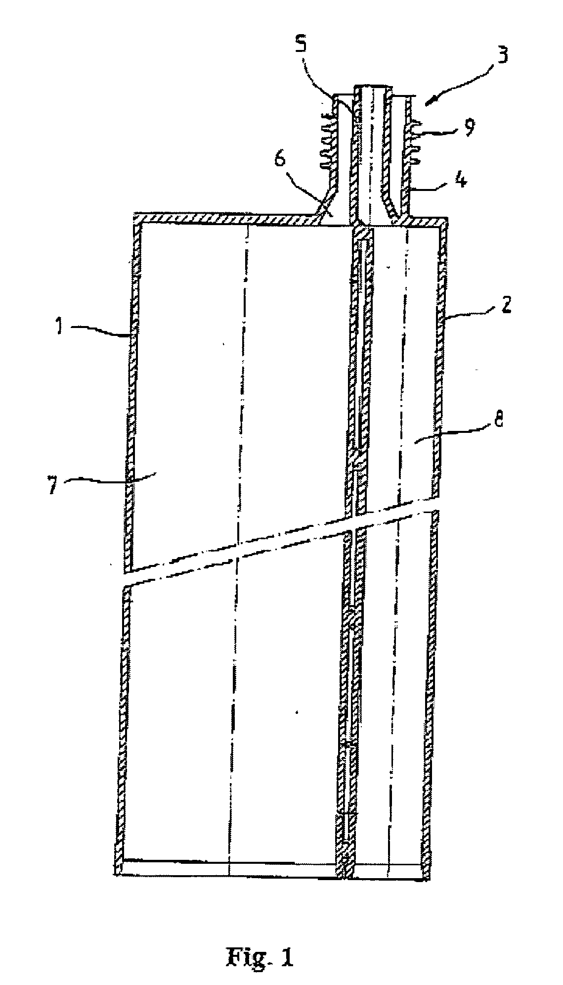
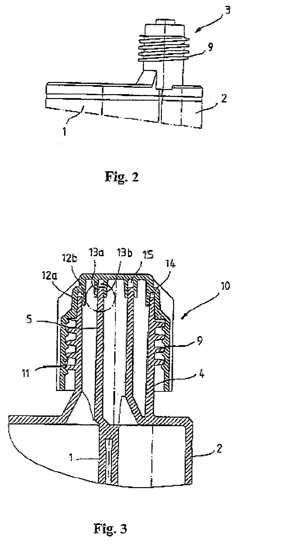
[0025]FIG. 1 shows a so-called side-by-side two-component cartridge. It consists of two hollow, cylindrical housings 1 and 2 arranged in parallel and side by side, and also a coaxial outlet 3 with an outer outlet tube 4 and an inner outlet tube 5 arranged concentrically inside the outer tube. Between the outer outlet tube 4 and the inner outlet tube 5, an annular channel 6 is defined, which connects to the interior 7 of the housing 1. The inner outlet tube 5 opens into the interior 8 of the housing 2. Thus, the materials located in the interiors 7 and 8 can still be discharged separately by means of the outer outlet tube 4 and the inner outlet tube 5, respectively, of the coaxial outlet 3.

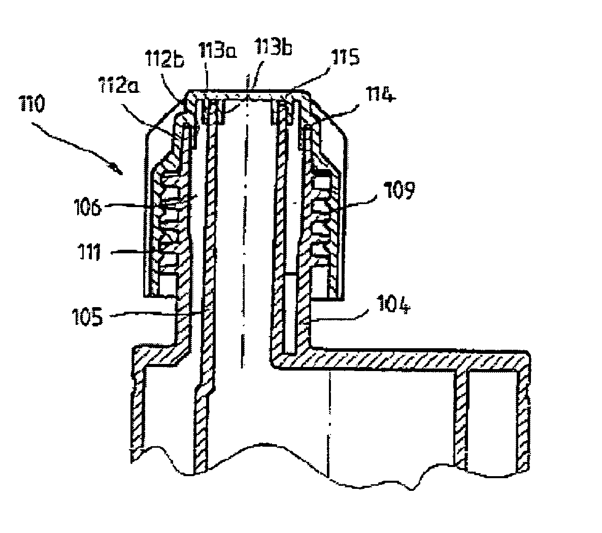
[0026] As can be gathered especially from FIG. 2, external threads 9, which are used for fastening a static mixer, which is known and therefore not shown, are formed on the outer side of the coaxial outlet 3. For the embodiment shown in FIGS. 1-3, the threads 9 are also used for fastening a cap 10...


PUM


Abstract

A multicomponent cartridge, particularly a two-component cartridge, contains a coaxial outlet with an outer outlet tube and an inner outlet tube concentric to the outer tube. A cap detachably connected to the coaxial outlet. A seal with at least one seal flange is arranged on the cap for contact on the inner and/or outer outlet tube. A simplified and improved seal is thus enabled, such that the seal includes at least one laterally projecting sealing edge, which extends around the inner and/or outer side of the inner and/or outer outlet tube of the coaxial outlet and/or on the side of the one or more seal flanges facing the outer and/or inner side of the inner and/or outer outlet tube.

Description

BACKGROUND OF THE INVENTION [0001] 1. Field of the Invention [0002] The invention relates to a novel multicomponent cartridge, especially a two-component cartridge. [0003] 2. Prior Art [0004] Such cartridges are used, e.g., for preserving and storing multicomponent adhesives, curing sealants, resins, or the like. The components are first mixed when squeezed out of the cartridge into a separate static mixer, which is set on the cartridge. Typical multicomponent cartridges have separate material receptacles and a material outlet with a seal that can be removed before use. This seal is removed first before emptying the cartridge and can be configured, e.g., as a screw cap, a tear-off seal, or the like. The material receptacles for such cartridges lie either side by side (side-by-side cartridge) or are configured as coaxial tubes (coaxial cartridge). In either embodiment, the material outlet can be configured as a coaxial outlet. In this way, the first component is discharged through a ...

Claims


Application Information

Patent Timeline
Patent Type & Authority Applications(United States)
IPC IPC(8): B05C17/005B65D81/32
CPCB05C17/00506B05C17/00516B05C17/0052B65D81/3283B65D81/3227B65D81/325B05C17/00553B05C17/00596
Inventor BRUGNER, NIKOLAUS
Owner SULZER CHEMTECH AG
Why Eureka
Try Eureka