Agitating mill

a technology of agitating mill and agitating plate, which is applied in the direction of mixer accessories, mixers, mixing, etc., can solve the problems of achieve the effect of reducing technical complexity and saving a large amount of assembly tim

Inactive Publication Date: 2005-03-10
NETZSCH FEINMAHL TECH GMBH +1
View PDF4 Cites 12 Cited by
  • Summary
  • Abstract
  • Description
  • Claims
  • Application Information

AI Technical Summary

Benefits of technology

[0007] The achievement of the object according to the present invention is to assemble a disk-shaped milling element from multiple disk segments. In this way, the possibility arises of replacing them individually in the event of wear and / or breakage of milling disks, without the removal of the agitating shaft and / or taking off all or multiple milling elements always being necessary. Particularly for large agitating mills having a large diameter of the milling elements, this saves a large amount of assembly time. For example, using this ability, milling elements from wear-intensive milling zones may also be exchanged after a specific number of operating hours with milling elements from low-wear milling zones. For the assembly and / or dismantling of milling elements having up to 2 m cross-section or more, the weight of the milling elements also plays an essential role. If the milling elements are made of multiple disk segments, this naturally also reduces the technical complexity during the replacement procedure.
[0008] According to a refinement of the present invention, the milling elements may also be provided with a single or multipart hub. The advantage in the use of a hub separable from the disk segments is that the hub may be manufactured from a different material and may thus be designed for different load criteria.

Problems solved by technology

Particularly for large agitating mills having a large diameter of the milling elements, this saves a large amount of assembly time.

Method used


Image

  • Agitating mill
  • Agitating mill
  • Agitating mill

Examples


Embodiment Construction

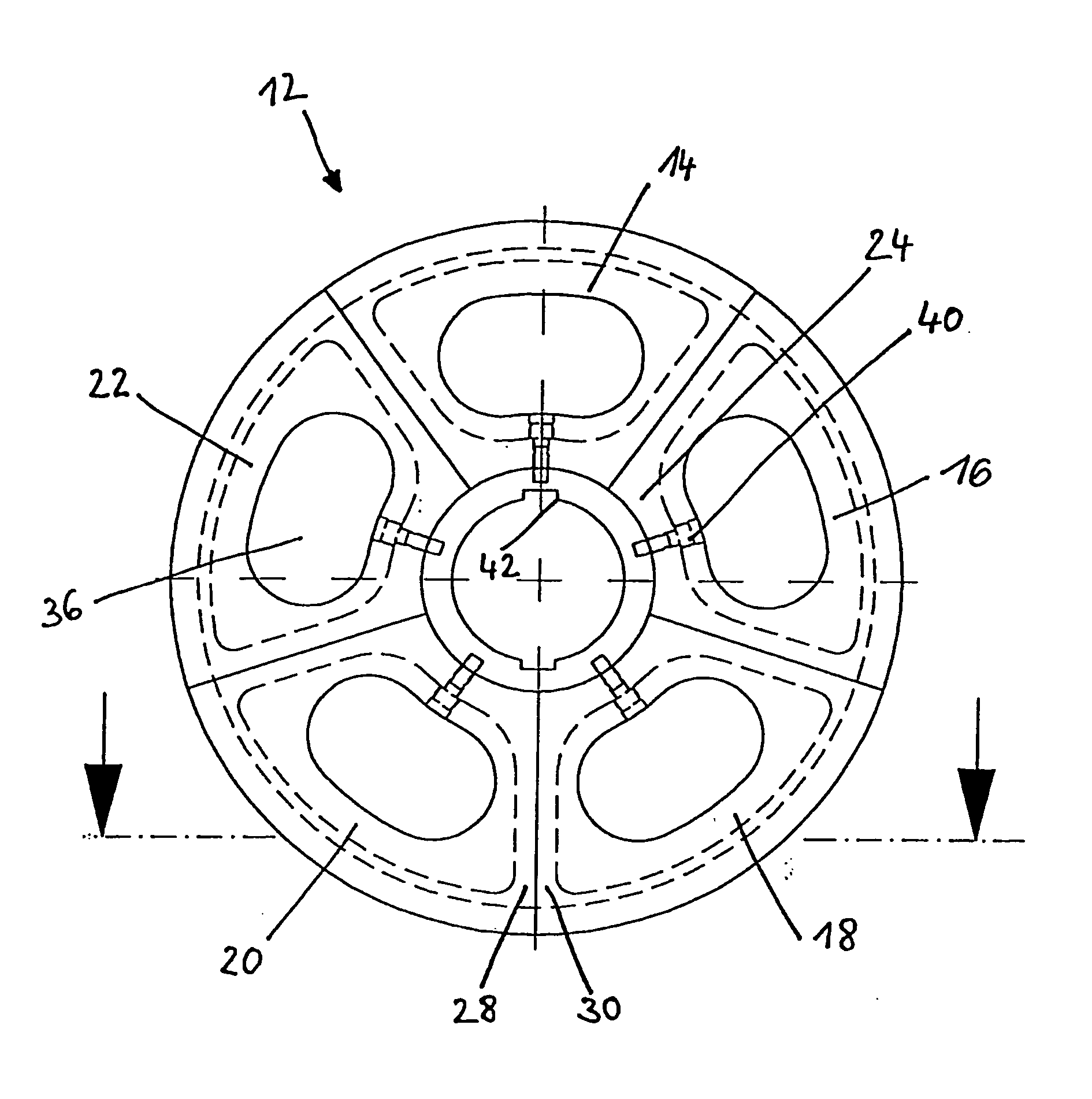
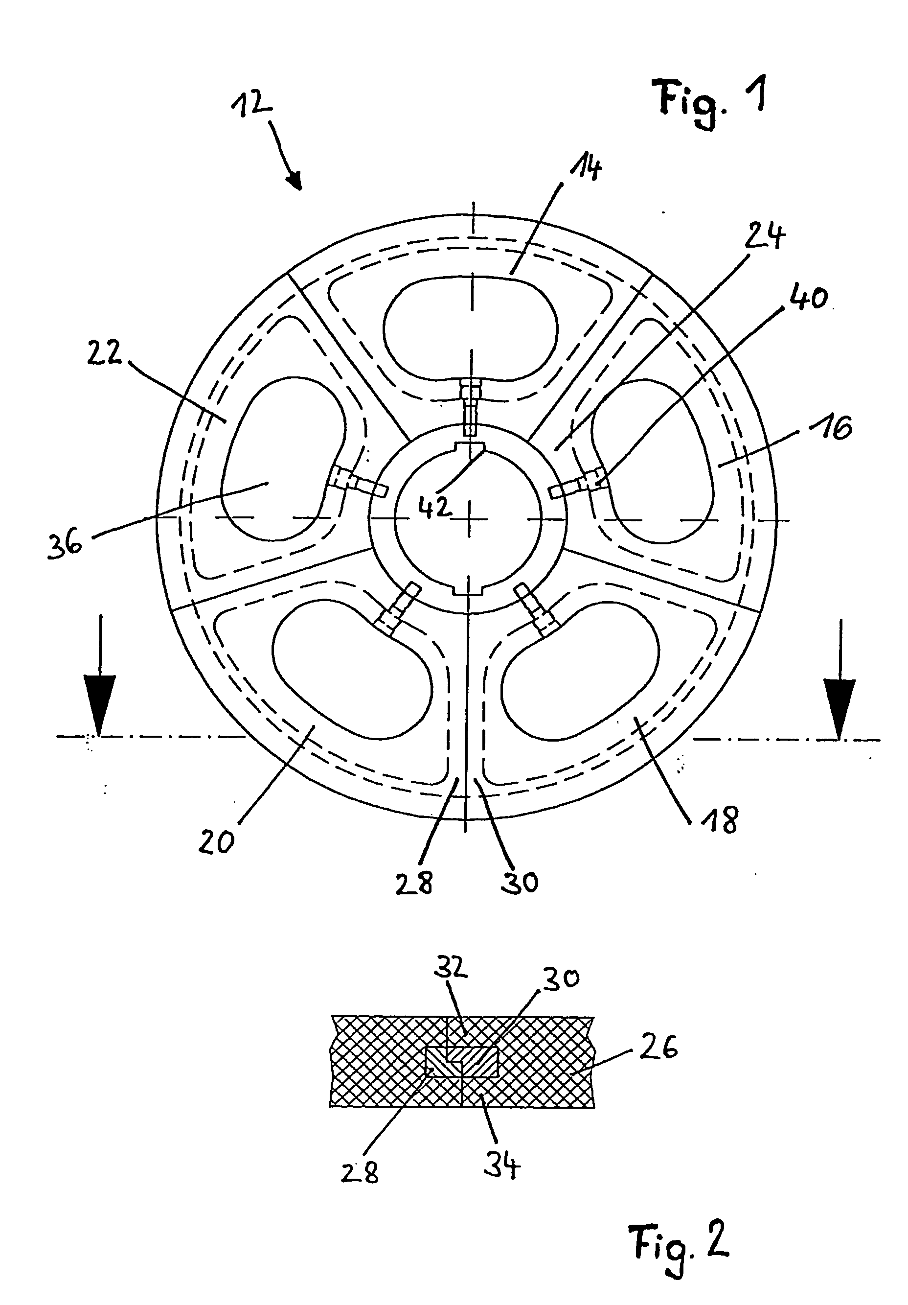
[0023]FIG. 1 shows a milling element 12, including five disk segments 14, 16, 18, 20, 22. The disk segments have a disk core 24, which is enclosed by a plastic or rubber coating 26. The disk segments are provided on their legs 28, 30, as also shown in FIG. 2, with projections 32 and recesses 34, which ensure the axial support of the disk transitions. To elevate the milling and mixing performance which the milling elements transfer to the milled product / milling body mixture, the disk segments 14, 16, 18, 20, 22 have oblong openings 36. The five disk segments 14 through 22 and the centrally positioned one-piece hub are connected to one another by screws 40. The form fit between the drive shaft and the hub 32 arises through the insertion of a spring into the groove 42.

[0024] Depending on how the transition of the disk segments 14, 16, 18, 20, 22 is designed, in a butted embodiment in the example shown in FIG. 2, the attachment changes between the disk segments 14, 16, 18, 20, 22 and t...


PUM


Abstract

The invention relates to an agitating mill, in which the agitating shaft is provided with several disc-type milling elements. In previous models the milling discs were replaced by being removed disc by disc from the shaft, together with any spacers that were arranged in between and new discs were then mounted. According to the invention, the milling elements consist of several disc segments, which permits the replacement of individual milling elements without having to dismantle additional milling elements on the shaft.

Description

PRIORITY APPLICATION [0001] The present application claims priority to German application no. 10219482.3 filed Apr. 30, 2002 and PCT application no. PCT / DE03 / 01369 filed Apr. 30, 2003, published in the German language on Nov. 13, 2003 as WO 03 / 092897. BACKGROUND OF THE INVENTION [0002] 1. Field of the Invention [0003] The present invention relates to an agitating mill having a milling container and an agitating shaft rotating therein, on which multiple disk-shaped milling elements are positioned in a row. [0004] 2. Description of the Related Art [0005] An agitating mill, in which an agitating shaft is positioned in the milling chamber, is known from U.S. Pat. No. 4,513,917. The agitating shaft carries multiple disk-shaped milling elements spaced axially apart from one another. Each of the milling elements is radially delimited by an edge bead. Between this edge bead and a hub, which is connected to the agitating shaft by a pin connection, the milling element has circular openings. T...

Claims


Application Information

Patent Timeline
Patent Type & Authority Applications(United States)
IPC IPC(8): B01F7/00B01F13/10B01F15/00B02C17/16
CPCB01F7/00025B01F7/001B01F7/0045B02C17/163B01F13/1044B01F2013/1086B01F7/00458B01F27/052B01F27/071B01F27/115B01F27/1151B01F33/8305B01F33/83613
Inventor ENDERLE, UDOSUK, JOCHEN
Owner NETZSCH FEINMAHL TECH GMBH
Why Eureka
Try Eureka