
Transmissive optical elements including transparent plastic shell having a phosphor dispersed therein, and methods of fabricating same

Active Publication Date: 2005-03-10
CREELED INC
View PDF61 Cites 117 Cited by
  • Summary
  • Abstract
  • Description
  • Claims
  • Application Information

AI Technical Summary

Problems solved by technology

Packaging may constitute a major portion of the expense and / or fabrication time for a finished light emitting device.

Method used


Image

  • Transmissive optical elements including transparent plastic shell having a phosphor dispersed therein, and methods of fabricating same
  • Transmissive optical elements including transparent plastic shell having a phosphor dispersed therein, and methods of fabricating same
  • Transmissive optical elements including transparent plastic shell having a phosphor dispersed therein, and methods of fabricating same

Examples


Embodiment Construction

[0017] The present invention now will be described more fully hereinafter with reference to the accompanying drawings, in which embodiments of the invention are shown. This invention may, however, be embodied in many different forms and should not be construed as limited to the embodiments set forth herein. Rather, these embodiments are provided so that this disclosure will be thorough and complete, and will fully convey the scope of the invention to those skilled in the art. In the drawings, the size and relative sizes of layers and regions may be exaggerated for clarity. Like numbers refer to like elements throughout.

[0018] It will be understood that when an element such as a layer, region or substrate is referred to as being “on” another element, it can be directly on the other element or intervening elements may also be present. It will be understood that if part of an element, such as a surface of a conductive line, is referred to as “outer,” it is closer to the outside of the...


PUM

PropertyMeasurementUnit
transparentaaaaaaaaaa
frequency bandaaaaaaaaaa
fabrication timeaaaaaaaaaa

Abstract

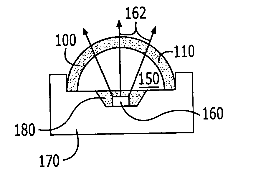
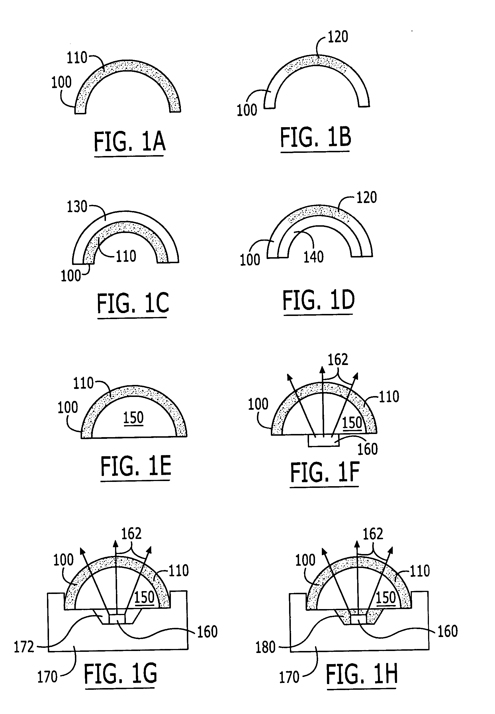
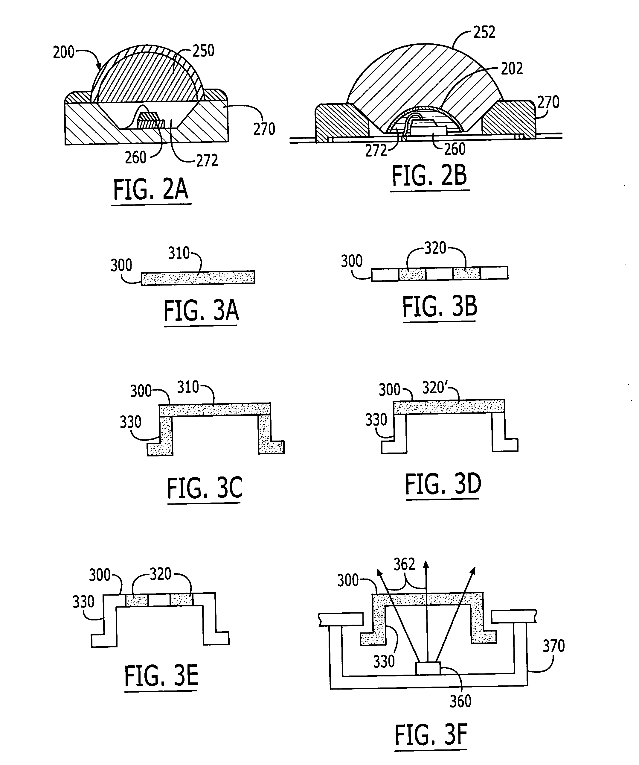
A transmissive optical element is fabricated by filling a mold with molten liquid that includes a transparent plastic and a phosphor additive, and allowing the molten liquid to solidify to produce the transmissive optical element having phosphor dispersed therein. Accordingly, a separate phosphor coating or phosphor-containing encapsulant need not be used. Transmissive optical elements include a shell made of transparent plastic with a phosphor dispersed therein. The phosphor may be uniformly and / or nonuniformly dispersed in the shell.

Description

FIELD OF THE INVENTION [0001] This invention relates to light emitting devices and fabricating methods therefor, and more particularly to packaging and packaging methods for light emitting devices. BACKGROUND OF THE INVENTION [0002] Semiconductor light emitting devices such as Light Emitting Diodes (LED) or laser diodes are widely used for many applications. As is well known to those having skill in the art, a semiconductor light emitting diode is generally packaged by at least partially surrounding the semiconductor light emitting diode with a dome-shaped transparent plastic shell. [0003] It is often desirable to incorporate a phosphor into the light emitting device, to enhance the emitted radiation in a particular frequency band and / or to convert at least some of the radiation to another frequency band. Phosphors may be included in a light emitting device using many conventional techniques. In one technique, phosphor is coated inside and / or outside the plastic shell. In other tech...

Claims


Application Information

Patent Timeline
Patent Type & Authority Applications(United States)
IPC IPC(8): B29C39/00B29C45/00H01H13/83H01L33/50H01L33/58
CPCB29C39/003B29C45/0001H01L2224/48091B29D11/0074B29K2995/0018B29L2011/00B29L2031/3431H01H13/83H01H2219/014H01H2219/052H01H2221/07H01H2229/046H01L33/505H01L33/507H01L33/58H01L2924/00014
Inventor NEGLEY, GERALD H.LOH, BAN
Owner CREELED INC
Learn More