Wide bandgap transistor devices with field plates

a transistor and field plate technology, applied in the field of transistors, can solve the problems of low electron mobility, limiting the performance of gan based transistors, and degrading the high performance gain of si based hemt, and achieve the effect of improving operating characteristics

Active Publication Date: 2005-03-10
CREE INC
View PDF33 Cites 193 Cited by
  • Summary
  • Abstract
  • Description
  • Claims
  • Application Information

AI Technical Summary

Benefits of technology

This patent describes an improvement for making better transistors that use special fields to help them work more efficiently. These improvements involve adding extra materials called field plates to certain parts of the transistor structure. By doing this, researchers hope they can create devices that are faster, have less resistance, and be easier to control.

Problems solved by technology

The technical problem addressed in this patent text relates to improving the performance of galvan nitride (AlGaN/GaN)-based heated metal layer (HEMT) transistors used in high-frequency, high-power electronic applications. Specifically, the text discusses issues related to electron trapping and its impact on device performance, including reduced efficiency and increased noise under radio frequency conditions. Additionally, the text describes various techniques for addressing these challenges, such as silicon nitride passivation and reduction of surface charges through use of insulating films.

Method used


Image

  • Wide bandgap transistor devices with field plates
  • Wide bandgap transistor devices with field plates
  • Wide bandgap transistor devices with field plates

Examples


Embodiment Construction

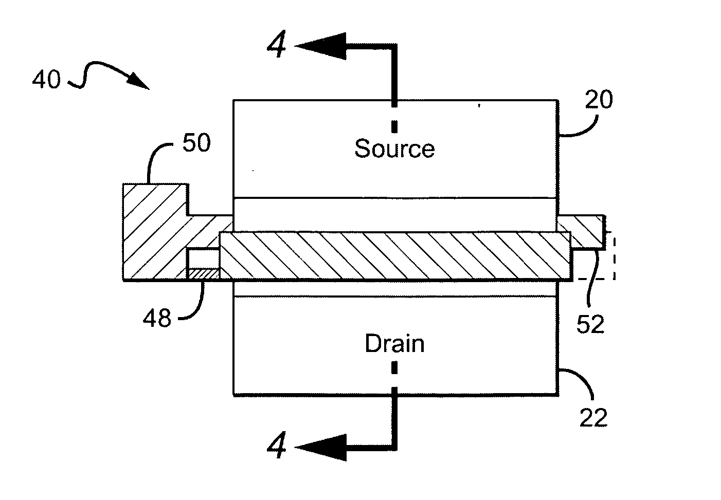
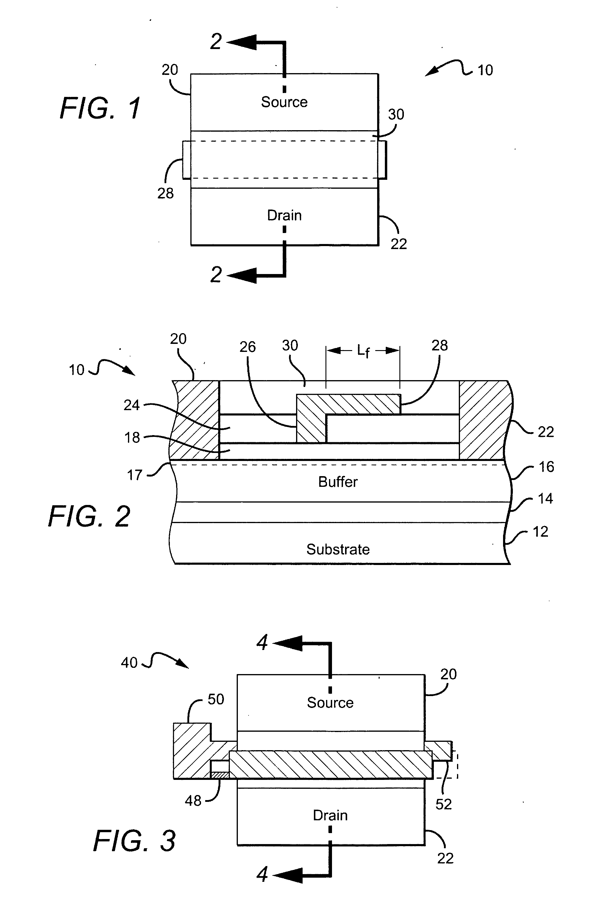
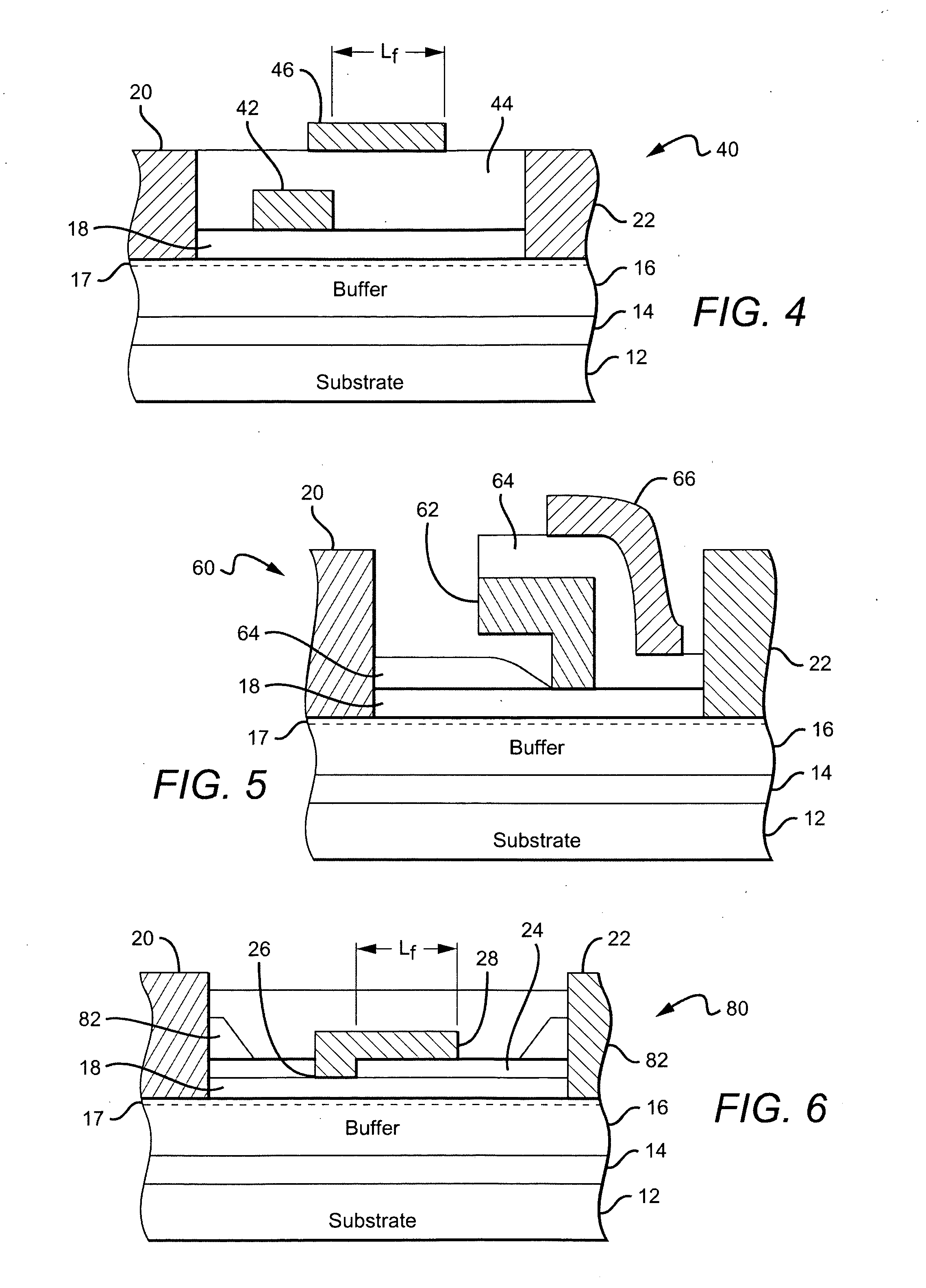
[0028] The field plate arrangements according to the present invention can be used with many different transistor structures. Wide bandgap transistor structures generally include an active region, with metal source and drain contacts formed in electrical contact with the active region, and a gate contact formed between the source and drain contacts for modulating electric fields within the active region. A spacer layer is formed above the active region. The spacer layer can comprise a dielectric layer, a layer of epitaxial material such as an undoped or depleted wide bandgap epitaxial material, or a combination thereof. A conductive field plate is formed above the spacer layer and extends a distance Lf from the edge of the gate contact toward the drain contact. The field plate can be electrically connected to the gate contact. This field plate arrangement can reduce the peak electric field in the device, resulting in increased breakdown voltage and reduced trapping. The reduction of...


PUM


Abstract

A transistor structure comprising an active semiconductor layer with metal source and drain contacts formed in electrical contact with the active layer. A gate contact is formed between the source and drain contacts for modulating electric fields within the active layer. A spacer layer is formed above the active layer and a conductive field plate formed above the spacer layer, extending a distance Lf from the edge of the gate contact toward the drain contact. The field plate is electrically connected to the gate contact.

Description


Claims


Application Information

Patent Timeline
Owner CREE INC
Why Eureka
Try Eureka