Multifocal optical device design

a multi-focal, optical device technology, applied in the direction of design optimisation/simulation, instruments, spectacles/goggles, etc., can solve the problems of low astigmatism control, distortion and color fringing, and high astigmatism level, so as to reduce computation time and achieve accurate powers.

Inactive Publication Date: 2005-03-10
RGT UNIV OF MINNESOTA
View PDF10 Cites 15 Cited by
  • Summary
  • Abstract
  • Description
  • Claims
  • Application Information

AI Technical Summary

Benefits of technology

We offer an indirect way to design progressive optical devices that reduces computation time for accurate powers and small undesired astigmatism. Input parameters comprise a prescribed power distribution, a weight function for power deviation, and one for astigmatism. We solve a linearized variational equation as perturbations over a base surface, and may express the solution in terms of superposed low-degree splines.

Problems solved by technology

Astigmatism is normally an undesirable property of lenses that causes distortion and color fringing.
Direct methods usually result in a high astigmatism level with little control over the astigmatism in different areas of the lens surface.
Indirect methods balance a desired power distribution with the unavoidable astigmatism produced.
Indirect methods involve the solution of fourth-order nonlinear elliptic equations, which involve very large amounts of computation—up to several hours for a single lens design.
However, progressive design techniques have heretofore not integrated astigmatism correction, and fabricating the two corrections sequentially on the same surface would unacceptably thin the lens or device.
Although this makes the two corrections approximately independent of each other, some offset errors still exist, and structural weakness may still occur, especially in currently fashionable thin, light ophthalmic lenses.

Method used


Image

  • Multifocal optical device design
  • Multifocal optical device design
  • Multifocal optical device design

Examples


Embodiment Construction

Progressive Correction

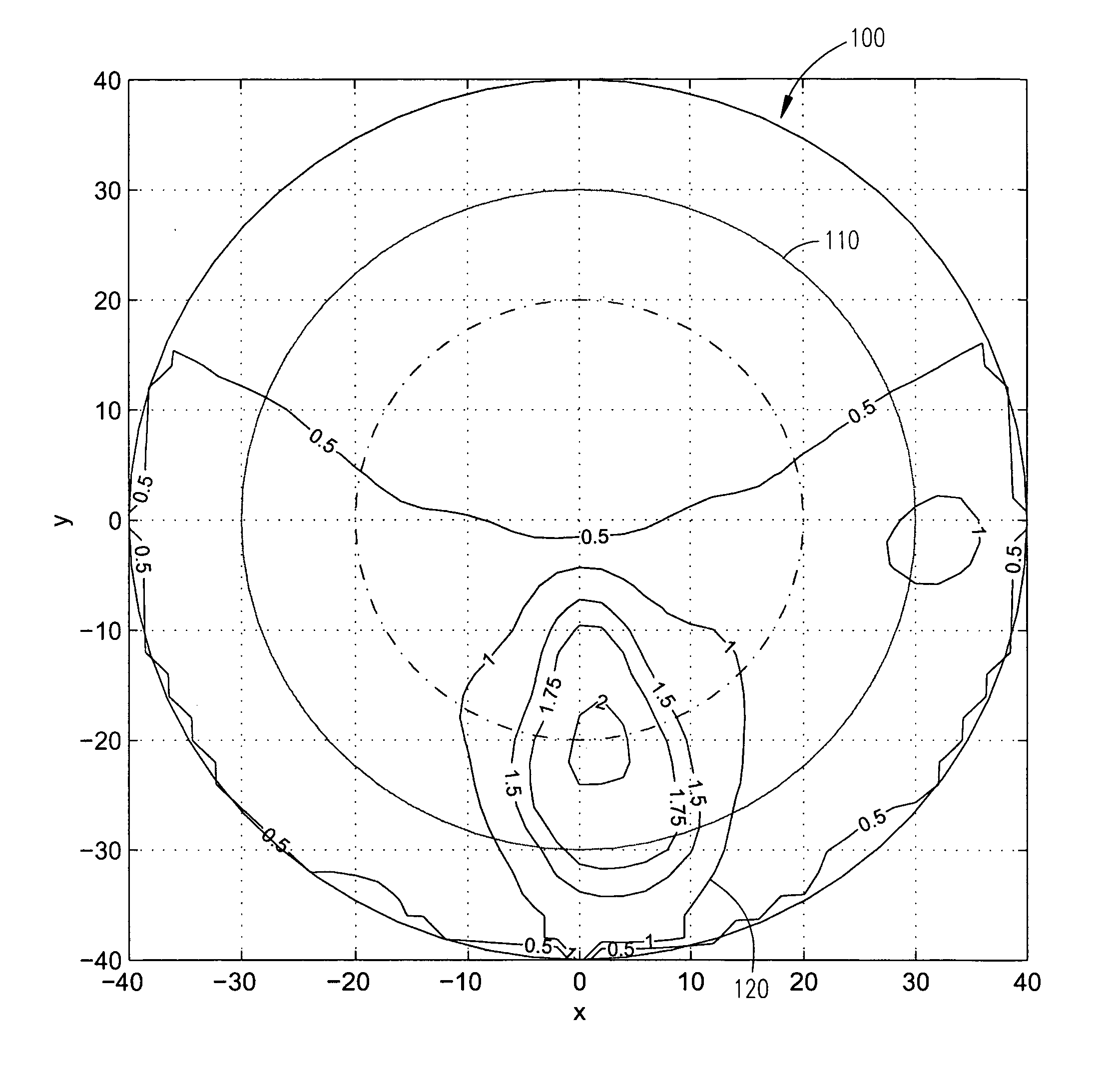
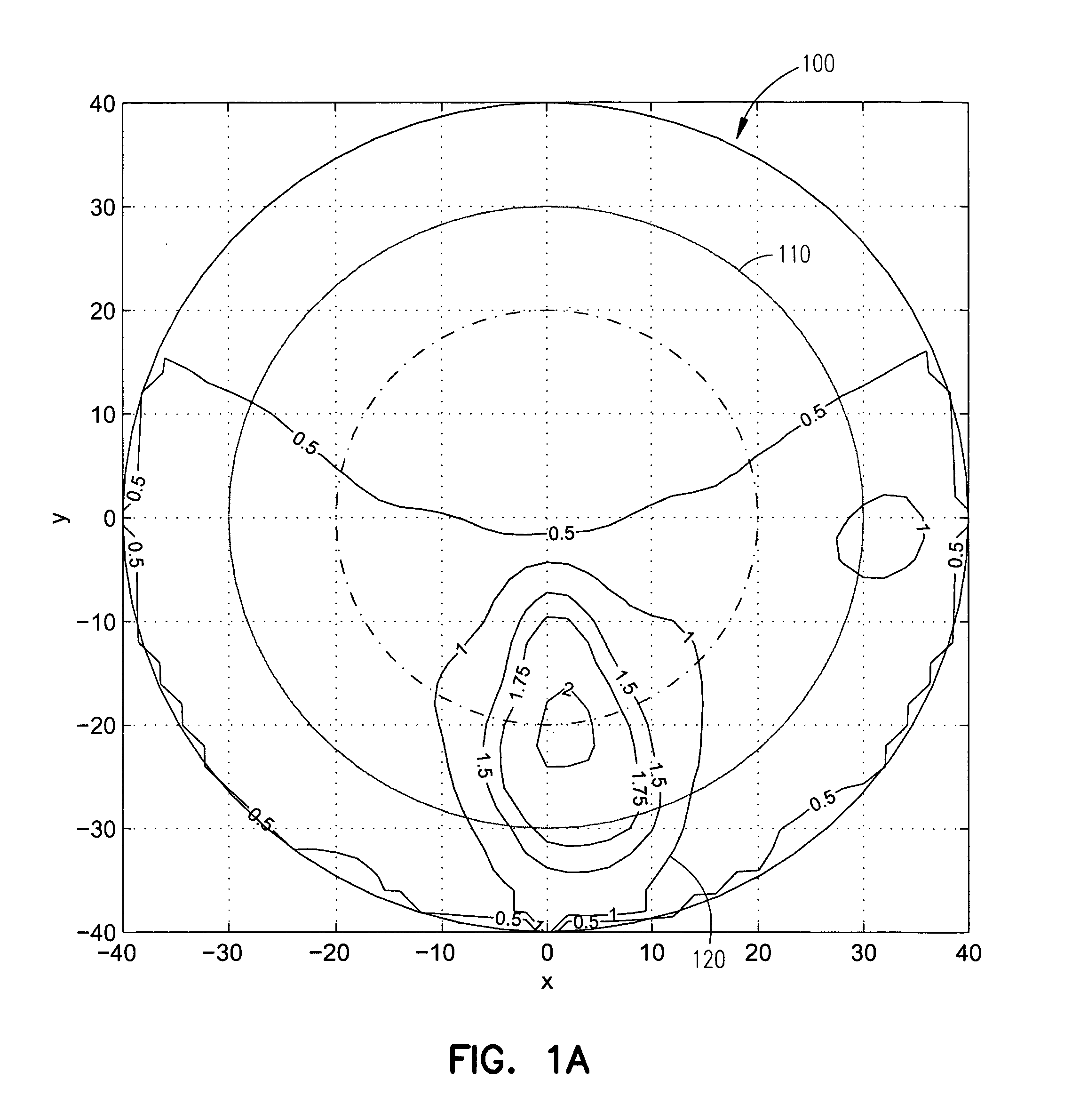
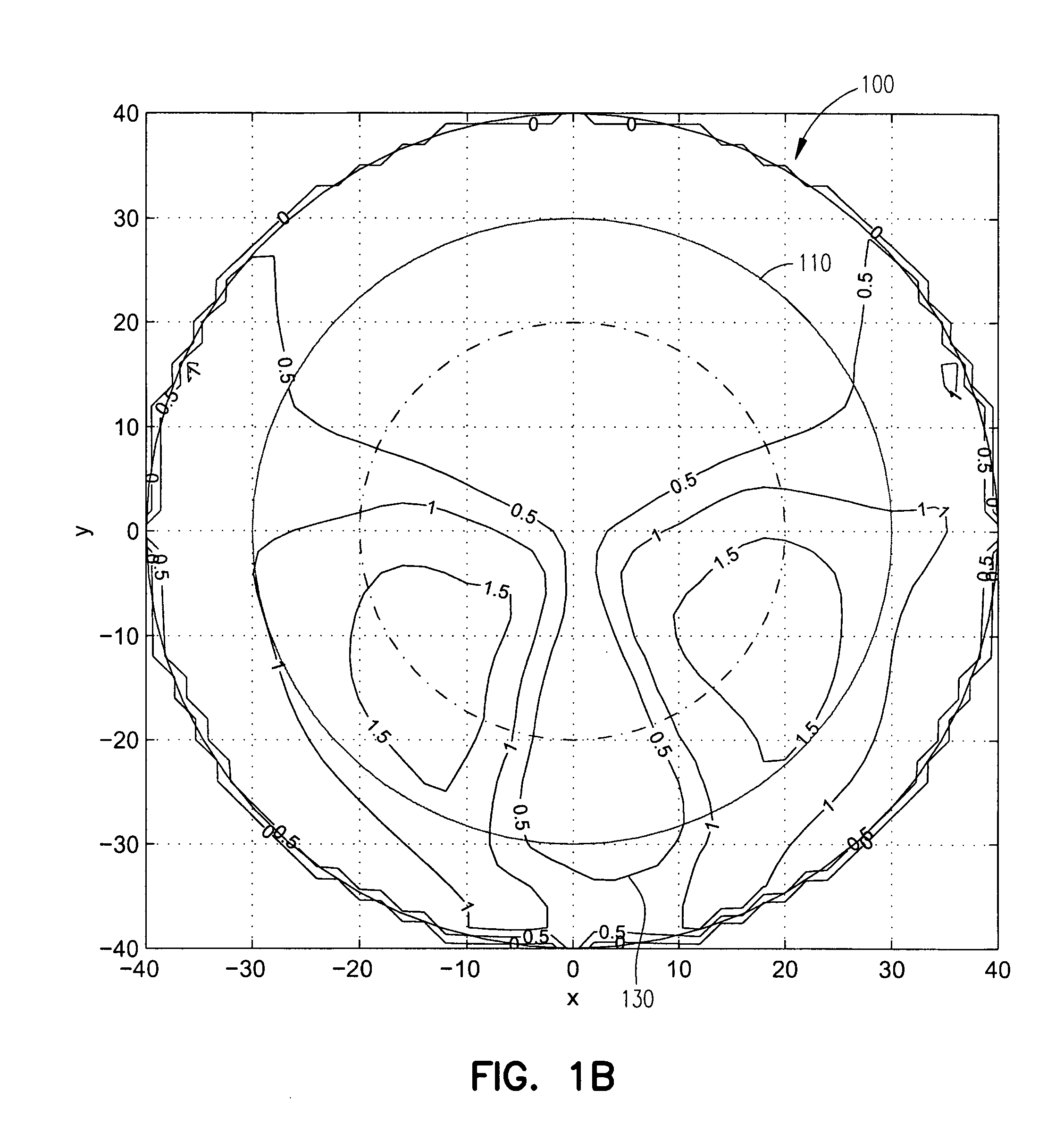
FIG. 1 shows an example ophthalmic progressive addition lens (PAL) 100 inside an edge 110. This lens typifies designs made with our procedure, although other optical devices can be produced in a similar manner. The coordinate axes denote millimeters from the center of the lens. FIG. 1A includes contour lines 120 having constant optical power. The mean power of an optical surface at a point x,y is proportional to the sum of the curvatures in two perpendicular directions at that point; the mean curvature is defined as H(x,y)=(k1(x,y)+k2(x,y)) / 2. In the example lens 100, the add power is 0.00 diopter in the far-view upper part of the lens. The near-view add power is 2.0 diopters in the bottom center of the lens. (“Add power” is the power that must be added to the far-view power to obtain the desired near-view power; in this example, the base or far-view power is 4.94.) A vertical corridor between the near-view and far-view portions has powers intermediate the two...


PUM


Abstract

Multifocal optical device designs receive input parameters to specify a desired power distribution function, a power deviation weight function, and an astigmatism weight function over the design field. A fourth-order partial differential variational equation is linearized by defining the optical surface in terms of perturbations from a base surface such as a sphere or a toric. The solution may be expressed as piecewise quadratic splines superposed over a triangulation of the field. Evaluation of the surface may use a set of tensor-product splines. An astigmatic base surface permits both multiple magnifying powers and a prescribed astigmatism correction in a single optical surface.

Description

TECHNICAL FIELD The present invention relates to computer-implemented methods and systems for designing optical devices, and particularly concerns the design of multifocal devices such as progressive ophthalmic lenses. BACKGROUND Multifocal optical devices find utility in a number of technologies. For example, bifocal and trifocal lenses treat presbyopia caused by loss of accommodative power of the eye. Progressive addition lenses for this purpose include a far-view zone with a low power for distance vision and a near-view zone with higher power for reading and other close work. The power increases progressively and smoothly in an intermediate zone or corridor between the far and near zones. Normally, the near zone lies near the bottom center of the lens, below the far zone; however, other arrangements satisfy specialized purposes. Lens design generates a specification of surface points that a grinder can produce from a lens blank. Modern lens grinders are numerically controlled ...

Claims


Application Information

Patent Timeline
Patent Type & Authority Applications(United States)
IPC IPC(8): G02C7/02G02C7/06
CPCG02C7/024G02C7/028G06F17/5009G02C7/061G02C7/06G06F30/20
Inventor WANG, JINGSANTOSA, FADILGULLIVER, ROBERT D.
Owner RGT UNIV OF MINNESOTA
Why Eureka
Try Eureka