
Automatic sound field correction apparatus and computer program therefor

a sound field correction and automatic technology, applied in the field of automatic sound field correction system and sound field correction method, can solve the problems of difficulty in adjusting the phase characteristics, frequency characteristics, sound pressure levels, etc. of sounds reproduced by a plurality, affecting auditory sound quality, and not achieving the target frequency characteristics

Inactive Publication Date: 2005-03-10
PIONEER CORP
View PDF10 Cites 14 Cited by
  • Summary
  • Abstract
  • Description
  • Claims
  • Application Information

AI Technical Summary

Benefits of technology

[0008] The above are examples of problems to be solved by the present invention. The present invention has an object to provide an automatic sound field correction system capable of making such corrections that will give desired frequency characteristics mainly to direct sounds without influence from reverberant sounds as well as to provide a computer program therefor.

Problems solved by technology

That is, they are required to correct sound-field characteristics automatically because it is extremely difficult to adjust phase characteristics, frequency characteristics, sound pressure levels, etc. of sounds reproduced by a plurality of speakers even if a listener himself / herself operates an audio system to obtain an appropriate audio space.
Consequently, the frequency characteristics of signal transmission lines are adjusted in such a way that direct sounds from the speakers which greatly affect auditory sound quality, including a sense of presence and sense of orientation, do not attain target frequency characteristics.
Also, if reverberation characteristics differ among channels, direct sounds from the speakers seem differently among the channels when a sound source signal is reproduced, which is a problem.

Method used


Image

  • Automatic sound field correction apparatus and computer program therefor
  • Automatic sound field correction apparatus and computer program therefor
  • Automatic sound field correction apparatus and computer program therefor

Examples


examples

[0030] 1. System Configuration

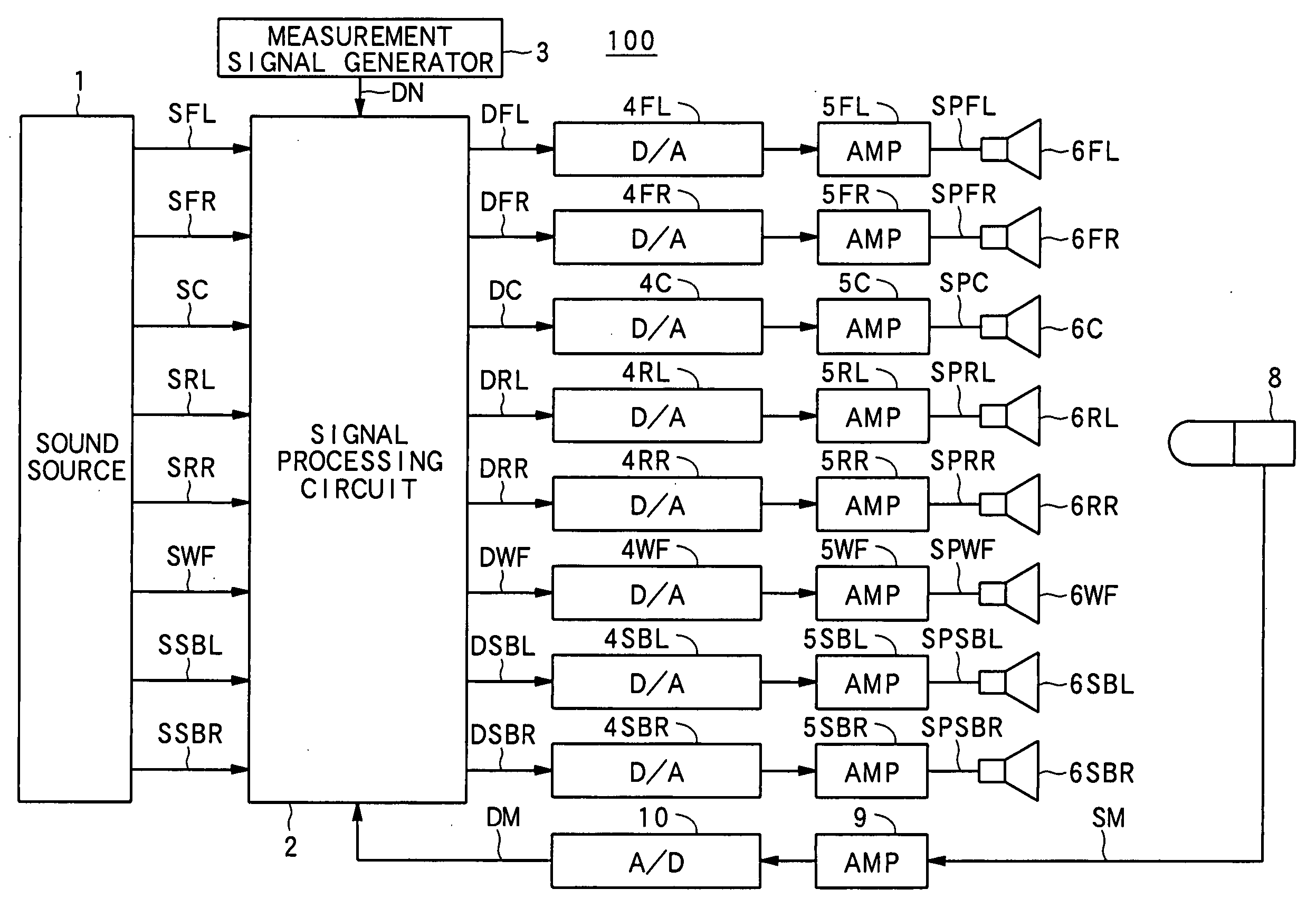
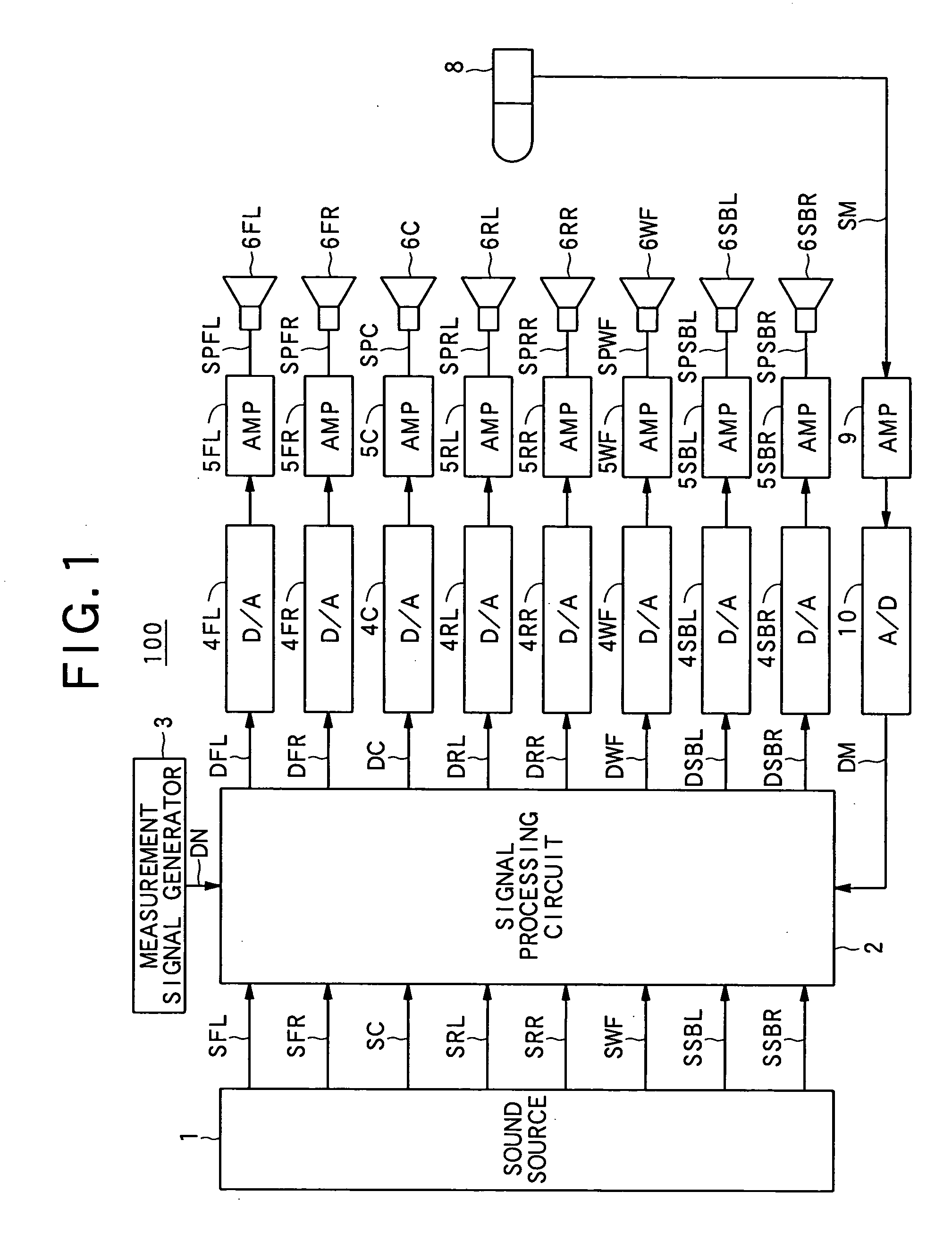
[0031] An example of the automatic sound field correction apparatus according to the present invention will be described below with reference to the drawings. FIG. 1 is a block diagram showing a configuration of an audio system equipped with the automatic sound field correction apparatus according to this example.

[0032] Referring to FIG. 1, the audio system 100 is equipped with a signal processing circuit 2 and measurement signal generator 3. The signal processing circuit 2 is fed digital audio signals SFL, SFR, SC, SRL, SRR, SWF, SSBL, and SSBR from a sound source 1 such as a CD (Compact Disc) player or DVD (Digital Video Disc or Digital Versatile Disc) via multi-channel signal transmission lines.

[0033] Incidentally, the audio system 100 includes multi-channel signal transmission lines and individual channels may be referred to as an “FL channel,”“FR channel,” etc. hereinafter. Also, when referring to all the channels in describing signals and compo...


PUM


Abstract

An automatic sound field correction apparatus processes multi-channel audio signals on respective signal transmission lines and reproduces them via a plurality of speakers. When adjusting frequency characteristics of the signal transmission lines, a measurement signal is supplied to the signal transmission lines and measurement signal sounds are emitted from the respective speakers. Then, the measurement signal sounds during a direct sound period are detected as detection signals by a detection device such as a microphone. Equalizer gain values are set appropriately based on the detection signals, thereby adjusting the frequency characteristics of the signal transmission lines. During the direct sound period in which the measurement signal sounds are detected, since the measurement signal sounds do not contain a reverberant component, the frequency characteristics of the signal transmission lines can be adjusted mainly using the direct sounds. Thus, it makes such corrections that will give desired frequency characteristics mainly to direct sounds without influence from reverberant sounds.

Description

BACKGROUND OF THE INVENTION [0001] 1. Field of the Invention [0002] The present invention relates to an automatic sound field correction system and sound field correction method which automatically correct sound-field characteristics of an audio system equipped with a plurality of speakers. [0003] 2. Description of the Related Art [0004] Audio systems which are equipped with a plurality of speakers and provide high-quality audio space are required to automatically create an appropriate audio space with a sense of presence. That is, they are required to correct sound-field characteristics automatically because it is extremely difficult to adjust phase characteristics, frequency characteristics, sound pressure levels, etc. of sounds reproduced by a plurality of speakers even if a listener himself / herself operates an audio system to obtain an appropriate audio space. [0005] Known automatic sound field correction systems of this type include a system disclosed in US2002-159605A (which i...

Claims


Application Information

Patent Timeline
Patent Type & Authority Applications(United States)
IPC IPC(8): G10K15/00H04S3/00H04S7/00H04R3/04
CPCH04S3/00H04S7/307H04S7/305H04S7/301
Inventor YOSHINO, HAJIME
Owner PIONEER CORP
Learn More