Methods of operating surface reactors and reactors employing such methods

a surface reactor and reactor technology, applied in the direction of liquid-gas reaction of thin-film type, heating type, separation process, etc., can solve the problems of high energy loss, slow process, and change the kind and quality of the resultant product, and achieve fast and high-rate conversion chemical reactions.

Active Publication Date: 2005-03-10
HOLL TECH CO KREIDO LAB +2
View PDF9 Cites 39 Cited by
  • Summary
  • Abstract
  • Description
  • Claims
  • Application Information

AI Technical Summary

Benefits of technology

[0011] It is an object of this invention to provide new methods of operating rotating surface reactors and reactors employing such methods facilitati...

Problems solved by technology

Bulk stirring is only able to present the opportunity for reagent molecules to contact one another after sufficient time has elapsed to provide the necessary uniformity of interdispersion of the reagents' molecules for achieving the desired one on one contact which finally makes a reaction possible, and only molecular diffusion can accomplish the required one on one contact, which is a very slow process.
In a stirred tank reactor (STR) the energy input clearly comes from the impeller, but this arrangement suffers from high energy losses through friction, macro-agitation, mere recirculation of the fluid, and other factors.
A further important disadvantage of bulk agitated chemical reaction systems is the fact that dimensional scaling up or down also changes t...

Method used


Image

  • Methods of operating surface reactors and reactors employing such methods
  • Methods of operating surface reactors and reactors employing such methods
  • Methods of operating surface reactors and reactors employing such methods

Examples


Embodiment Construction

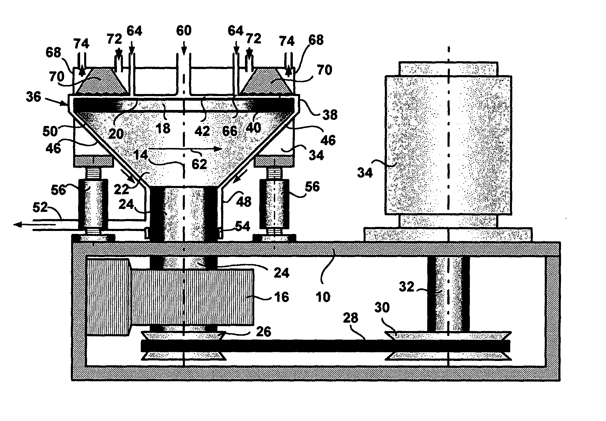
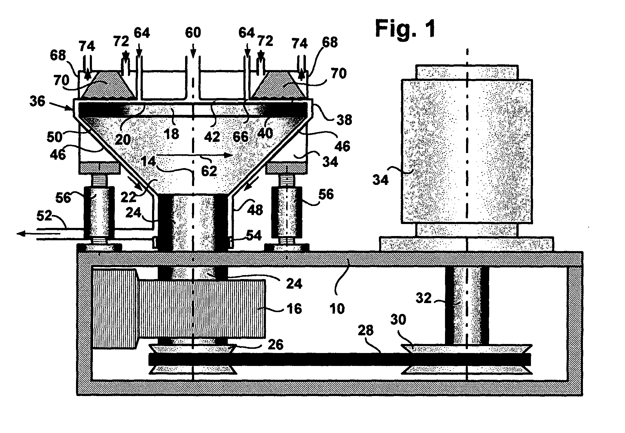
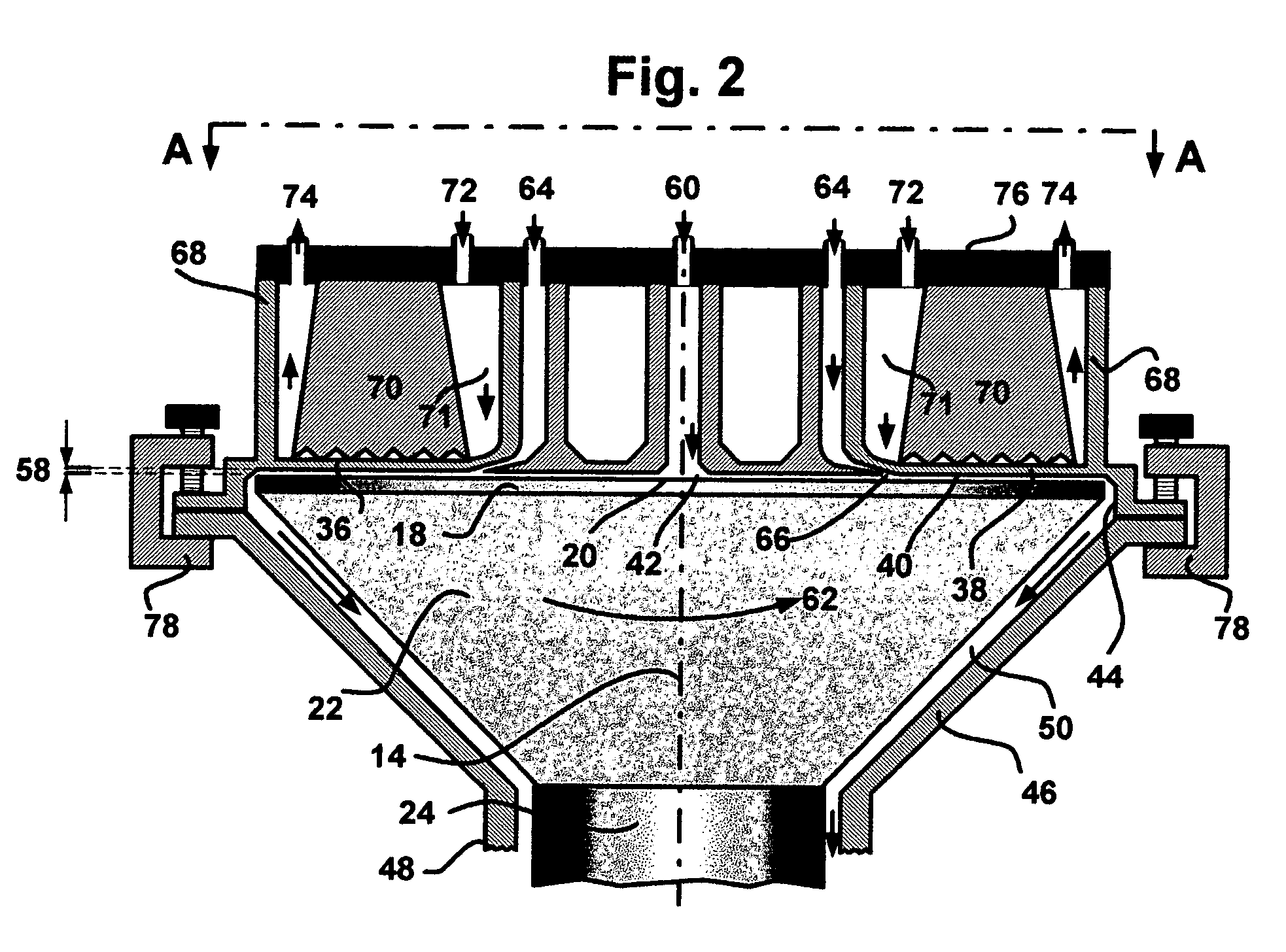
[0037] The apparatus is mounted on a base member 10 and in this embodiment comprising a rotor given the general reference 12 that is mounted on the base member for rotation about a vertical axis 14 by means of a bearing support 16. The rotor comprises a disc portion 18 having a flat circular upper reactor surface 20 with the axis 14 as its center or generation and rotation, the disc portion being mounted on the upper end of a frusto-conical connecting portion 22 of decreasing diameter downward. The connecting portion is in turn mounted on a cylindrical shaft portion 24 of uniform diameter along its length, this shaft portion being engaged in a bearing (not shown) carried by the bearing support 16. The lower end of the shaft portion carries a V-groove pulley 26 connected by a drive belt 28 to a similar pulley 30 mounted on drive shaft 32 of a controllable speed drive motor 34 mounted on the base member 10. If preferred, or in addition, the pulleys 26 and 30 and the drive belt 28 can ...


PUM

PropertyMeasurementUnit
Lengthaaaaaaaaaa
Lengthaaaaaaaaaa
Forceaaaaaaaaaa

Abstract

Methods of operating surface reactors, and such reactors, particularly spinning disc reactors require that a first reactant is fed to the reactor surface and forms a thin film on the surface. A second reactant is fed to the surface in the form of a second thin film to interact with the first film so as to overcome the impedance to interaction between the two films imposed by the existence of molecular clusters in the films. Thus, each film is fed into the receiving film at a rate such as to break up the molecular clusters in the film and thereby permit the molecules to aggressively and completely interact with one another. In the spinning disc apparatus the films are fed at respective distances from the spin axis. The interaction takes place in a thin chamber (less than 1 mm) between a retaining surface coextensive with the reactor surface whose distance from one another can be varied continuously, with the components being sheared between the surfaces to break up the molecular clusters to facilitate molecular, forced interdiffusion. Preferably each film is fed into the reaction chamber through a respective annular nozzle producing an improved uniformity of initial and continuous contacting of the reactants followed by an increase in forced interdiffusion of reactant molecules.

Description

FIELD OF THE INVENTION [0001] The invention is concerned with new methods of operating surface reactors, and with new reactors employing such methods, and especially but not exclusively to methods and reactors employing the so-called spinning disc technology. BACKGROUND OF THE INVENTION [0002] Chemical reactions cannot occur until individual molecules of the reagents are brought together, and physical interactions between components are greatly facilitated as the components are more and more intimately mixed together. Bulk stirring is only able to present the opportunity for reagent molecules to contact one another after sufficient time has elapsed to provide the necessary uniformity of interdispersion of the reagents' molecules for achieving the desired one on one contact which finally makes a reaction possible, and only molecular diffusion can accomplish the required one on one contact, which is a very slow process. These encounters can be helped to occur by establishing small sca...

Claims


Application Information

Patent Timeline
IPC IPC(8): B01F25/74B01J10/02B01J14/00B01J19/18
CPCB01F5/221B01F7/00758B01F7/00783B01F7/00791B01F7/008B01J2219/00085B01F7/00833B01F2215/0427B01J10/02B01J14/00B01J19/1887B01F7/00825B01F25/741B01F27/2713B01F27/2714B01F27/271B01F27/2723B01F27/2724B01F27/272
Inventor HOLL, RICHARD A.
Owner HOLL TECH CO KREIDO LAB
Why Eureka
Try Eureka