Magnetic toner, and developing apparatus and image forming apparatus using it

a developing apparatus and toner technology, applied in the field of magnetic toner, can solve the problems of deterioration of the carrier, variability of the mixing ratio between the toner and the carrier, and the development of the toner with a magnetic toner, and achieve the effect of less fogging and less reddish images

Inactive Publication Date: 2005-03-10
SUGIMOTO HIROKO +3
View PDF6 Cites 4 Cited by
  • Summary
  • Abstract
  • Description
  • Claims
  • Application Information

AI Technical Summary

Benefits of technology

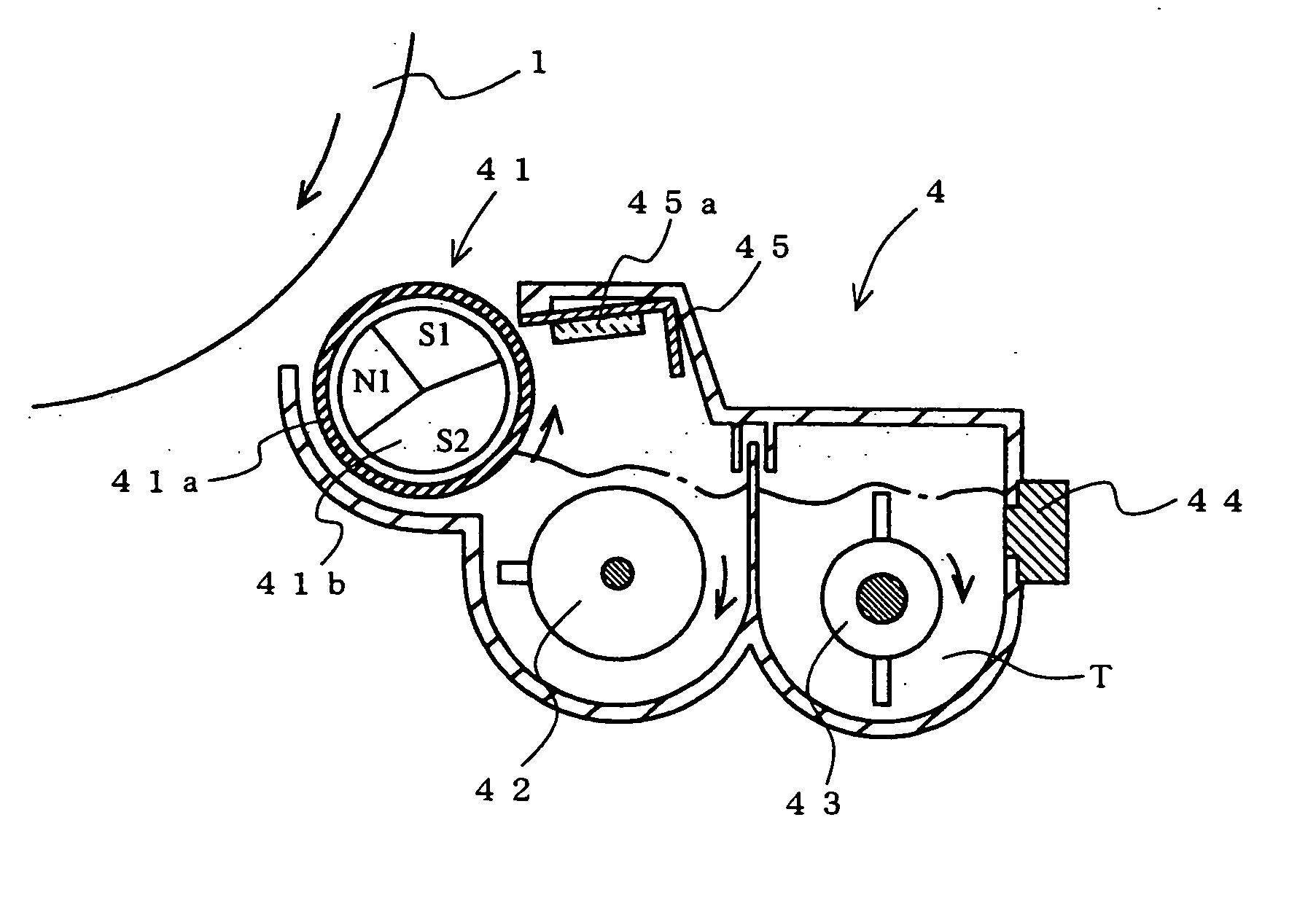
To achieve the above objects, according to another aspect of the present invention, in a developing apparatus and an image forming apparatus, a developing blade is provided that is fitted w...

Problems solved by technology

However, they are susceptible to variations in the mixing ratio between the toner and the carrier and to deterioration of the carrier.
However, in general, magnetic powders are not purely black but reddish, making images developed with a magnetic toner appear reddish.
That is, magnetic toners do not always offer a satisfac...

Method used


Image

  • Magnetic toner, and developing apparatus and image forming apparatus using it
  • Magnetic toner, and developing apparatus and image forming apparatus using it

Examples


example 1

Practical Example 1

Toner ingredients, specifically 100 parts by weight of styrene-acrylic resin serving as a binder resin, 5 parts by weight of a charge control agent, and 40 parts by weight of a magnetic powder (having an octahedral particle shape and an average particle diameter of 0.25 μm and containing 18% by weight of FeO), were put and mixed in a Henschel mixer, were then melt-kneaded in a twin-screw extruder, were then cooled in a drum flaker, and were then coarsely crushed on a hammer mill. The resultant granules were then finely crushed on a mechanical mill, and were then classified with a pneumatic classifier to obtain toner particles with a predetermined volume average particle diameter. These toner particles were blended with 0.6% by weight of silica (with a particle diameter of 0.012 μm), and were mixed through intense agitation in a Henschel mixer to obtain a magnetic toner that tends to be charged positively.

The bulk density of this magnetic toner was measured in t...

examples 2 to 7

Practical Examples 2 to 7 and Comparative Examples 1 to 8

With toners prepared so as to contain different types of magnetic powder and have different bulk densities as shown in Table 1, images produced with them were evaluated in the same manner as with Practical Example 1.

Table 1 shows the following. With the magnetic toners of Practical Examples 1 to 7, which are magnetic toners according to the present invention, image reddishness was alleviated to such a degree as to be ignorable in practical terms, and no background or partial fogging was observed. Nor was observed inadequate initial image density under high-temperature, high-humidity conditions. Moreover, with any of these magnetic toners, an image density of 1.3 was sustained after bulk printing on 10,000 sheets. With the magnetic toners of Practical Examples 1 to 4 and 6, an image density of 1.3 was sustained after bulk printing on 20,000 sheets. By contrast, with the magnetic toners of Comparative Examples 1 and 2, which ...


PUM


Abstract

A magnetic toner contains, as a magnetic powder, magnetic iron oxide having an octahedral particle shape and an average particle diameter of 0.21 μm or larger and containing 18% or more by weight of FeO. The magnetic toner is so prepared as to have a bulk density A (g/cm3) and a magnetic powder content B (% by weight) that fulfill the formulae 0.8≦A/B×100≦1.6 and 35≦B≦50. This alleviates the reddishness of images produced with the magnetic toner, and alleviates the disturbance of a thin toner layer on a developing sleeve and thus the fogging resulting therefrom.

Description

BACKGROUND OF THE INVENTION 1. Field of the Invention The present invention relates to a magnetic toner, and to a developing apparatus and an image forming apparatus using such a magnetic toner. 2. Description of the Prior Art Toners for use in the development of electrostatic latent images are roughly grouped into non-magnetic and magnetic toners. In image development, non-magnetic toners are usually used in the form of two-component developers, i.e., mixed with a carrier. Two-component developers maintain the electric charge of the toner stably, and thus offer satisfactory images for an extended period. However, they are susceptible to variations in the mixing ratio between the toner and the carrier and to deterioration of the carrier. On the other hand, magnetic toners are usually used singly, i.e., in the form of one-component developers. One-component developers, containing no carrier, permit size and weight reduction of developing apparatus, and do not require maintenance...

Claims


Application Information

Patent Timeline
IPC IPC(8): G03G9/08G03G9/083G03G15/08G03G15/09
CPCB82Y15/00G03G9/081G03G9/0817G03G9/0819G03G9/0821G03G2215/0602G03G9/0835G03G9/0836G03G9/0837G03G9/0838G03G15/09G03G9/0833
Inventor SUGIMOTO, HIROKONAGAI, TAKASHITAKATSUNA, TORUKIKUSHIMA, SEIJI
Owner SUGIMOTO HIROKO
Why Eureka
Try Eureka