Belt for electrophotography

Inactive Publication Date: 2005-02-08
CANON KK
View PDF9 Cites 6 Cited by
  • Summary
  • Abstract
  • Description
  • Claims
  • Application Information

AI Technical Summary

Benefits of technology

An object of the present invention is to provide an endless belt for electrophotography which is producible at a low cost and through a small number of steps and is rich in variety, and a process for its production.
Another object of the present invention is to provide an endless belt for electrophotography, and an image forming apparatus, which can obtain good color images with less color misregistration and less spots around line images.
Still another object of the present invention is to provide an endless belt for electrophotography which can be free from any changes in size and characteristics of the belt even with its repeated use and, after such use, can maintain the same characteristics as those at the initial stage, and to provide a process for its production and an image forming apparatus having such an endless belt.

Problems solved by technology

For example, intermediate transfer belts are required to have a surface area not smaller than the image region, so that they are necessarily large in size and also required to have various properties such as resistance properties and surface properties, tending to result in a high production cost.
They also have not necessarily a sufficient durability and tend to have to be frequently changed to new ones.
As the result, this may raise the main-body price and running cost of copying machines and printers and also it may take more time and labor for their maintenance.
In addition, in order to form good color images, some problems must be solved which may occur because a plurality of colors are superimposed on the intermediate transfer belt.
In fine lines and characters, even a slight color misregistration tends to be conspicuous to provide a possibility of damaging image quality.
The intermediate transfer belt is set across a plurality of shafts and is driven and rotated around them, where the tension applied to every part of the intermediate transfer belt is not necessarily uniform.
Hence, the intermediate transfer belt may undergo a local elongation and, concurrent therewith, may cause a delicately uneven rotation.
Another problem is occurrence of spots around line images.
Still another problem is half-tone image transfer performance.
Faulty images tend to occur when the intermediate transfer belt has uneven resistance or uneven thickness.
Any great change in size caused by the creep may make a difference from the original designing to aggravate color misregistration or may cause faulty images such as uneven halftone images.
It may also cause a difficulty in the rotation of the intermediate transfer belt, acting as a great factor to shorten the life of the intermediate transfer belt.
Making the belt thin-gage also has the effect of less causing a transfer toner scatter and is an effective means, but on the other hand tends to cause a problem also in respect of durability.
However, satisfying all of these high image quality, high durability, low cost and safety involves technical difficulties.
However, e.g., in the extrusion, the production of a thin-layer belt which enables reduction of cost and prevention of spots around line images involves considerable difficulties when the die gap of an extrusion die is merely set in the same size as the desired belt thickness to carry out extrusion.
Even if possible, such extrusion tends to cause uneven thickness and, as an effect thereof, uneven electrical resistance.
Also, processes making use of solvents as in cast molding, the coating and centrifugal molding require many steps of preparing a coating solution, coating the solution and removing the solvent, resulting in a high cost.

Method used


Image

  • Belt for electrophotography
  • Belt for electrophotography
  • Belt for electrophotography

Examples


example 1

Polysulfone100 partsConductive carbon black 16 parts

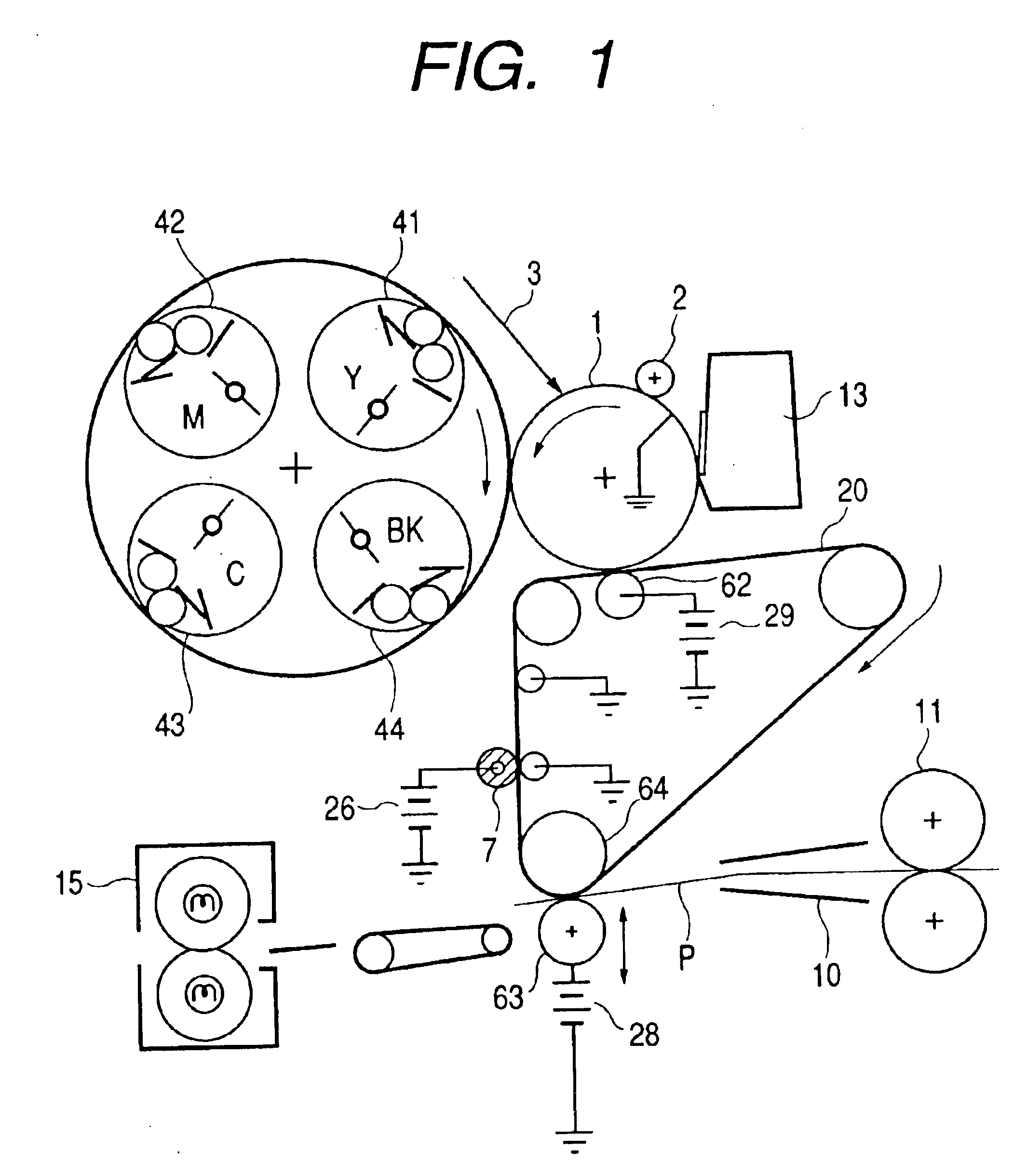
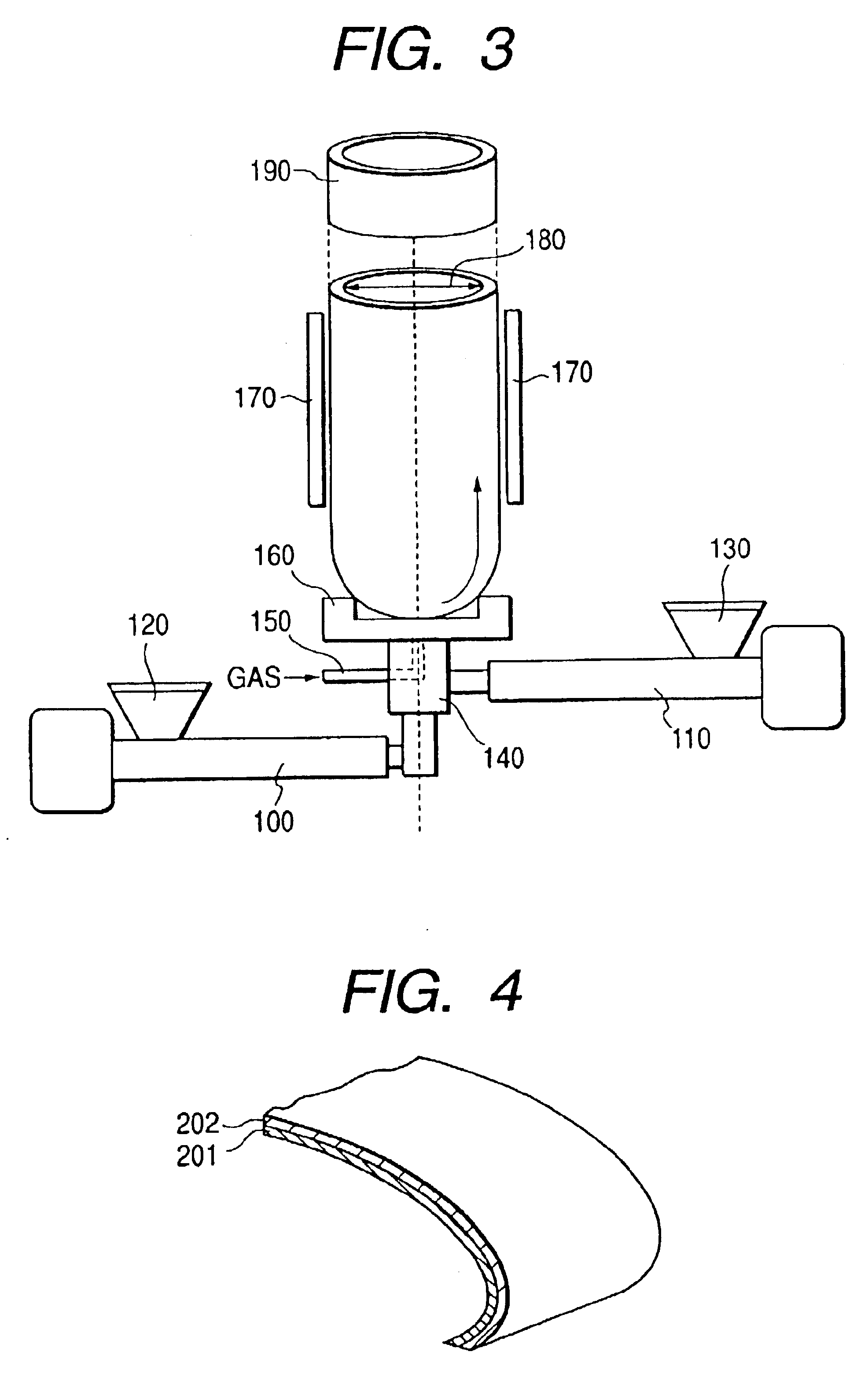
The above materials were kneaded by means of a twin-screw extruder, and the additive such as carbon black was well uniformly dispersed in the binder so as to provide the desired electrical resistance, thus an extrusion material (1) was obtained in the form of pellets of about 2 mm in diameter. Next, this extrusion material (1) was put into the hopper 120 of the single-screw extruder 100 shown in FIG. 3, and was extruded with heating to form a melt. The melt was subsequently brought to the circular die 140 for extruding a cylindrical single-layer product, having a diameter of 120 mm and a die gap of 1 mm. Then, air was blown from the gas inlet passage 150 while extruding the melt from the die, to scale-up inflate the extruded product into a cylindrical extruded product of 190 mm in diameter and 160 μm in thickness as final shape dimensions 180. This product was further cut in a belt width of 320 mm to obtain a seamless endless belt ...

example 2

Polysulfone80 partsPolyether sulfone20 partsConductive carbon black16 parts

The above materials were kneaded by means of a twin-screw extruder to obtain a uniform kneaded product, which was designated as an extrusion material (2). Next, this was continuously extruded by means of the extruder shown in FIG. 7, using a circular extrusion die 141 having a diameter of 200 mm and a die gap of 1.2 mm. The cylindrical extruded product obtained was cut to obtain an intermediate transfer belt (2) of 185 mm in diameter, 320 mm in belt width and 125 μm in thickness.

The tensile break strength and breaking extension of the extrusion material (2) were 80 MPa and 6%, respectively. The electrical resistance of the intermediate transfer belt (2) under application of 100 V was 3×10⁵ Ω.

The scattering of electrical resistance was within one figure in respect of both the surface-direction resistance and the thickness-direction resistance. The scattering of thickness was also as good as 125 μm plus-minus ...

example 3

Polyether sulfone80 partsPolybutylene terephthalate20 partsConductive carbon black15 parts

The above materials were kneaded by means of a twin-screw extruder to obtain a uniform kneaded product, which was designated as an extrusion material (3). The subsequent procedure of Example 1 was repeated to obtain an intermediate transfer belt (3) of 190 mm in diameter, 320 mm in belt width and 155 μm in thickness.

The electrical resistance of this intermediate transfer belt (3) under application of 100 V was 6×10⁵ Ω. The scattering of electrical resistance was within one figure in respect of both the surface-direction resistance and the thickness-direction resistance. The scattering of thickness was also as good as 155 μm plus-minus 11 μm. The tensile break strength and breaking extension of the extrusion material (3) were 71 MPa and 11%, respectively.

Next, using this intermediate transfer belt (3), printing was tested in the same manner as in Example 1 to obtain good results like those in Ex...


PUM

PropertyMeasurementUnit
Thicknessaaaaaaaaaa
Thicknessaaaaaaaaaa
Electrical resistanceaaaaaaaaaa

Abstract

An endless belt for electrophotography is disclosed which is obtainable continuously by melt extrusion from a circular die. The endless belt has a layer containing a thermoplastic resin having a diphenyl sulfone structure represented by the following Formula (1) Also disclosed are a process for producing the endless belt and an image forming apparatus having the endless belt.

Description

BACKGROUND OF THE INVENTION1. Field of the InventionThis invention relates to an endless belt for electrophotography, such as an intermediate transfer belt, a transfer material carrying belt or a photosensitive belt, a process for its production, and an image forming apparatus making use of it.2. Related Background ArtIntermediate transfer belts, transfer material carrying belts and photosensitive belts are known as endless belts for electrophotography.Compared with image forming apparatus in which images are transferred from a first image bearing member onto a second image bearing member (transfer material) fastened or attracted onto a transfer drum (e.g., Japanese Patent Application Laid-Open No. 63-301960), image forming apparatus making use of intermediate transfer belts have an advantage that a variety of second image bearing members can be selected without regard to their width and length, including thin paper (40 g / m2 paper) and up to thick paper (200 g / m2 paper) such as enve...

Claims


Application Information

Patent Timeline
IPC IPC(8): G03G5/05G03G15/16
CPCG03G5/0567G03G5/0582G03G15/162G03G15/1685Y10T428/2495Y10T428/24967
Inventor NAKAZAWA, AKIHIKOKOBAYASHI, HIROYUKISHIMOJO, MINORUSHIMADA, AKIRATANAKA, ATSUSHIASHIBE, TSUNENORIKUSABA, TAKASHIMATSUDA, HIDEKAZU
Owner CANON KK
Why Eureka
Try Eureka