
Fluidics circuit of hematology analyzer with heated reaction chamber

a technology of reaction chamber and fluidic circuit, which is applied in the field of hematology analyzers, can solve the problems relatively poor heat conductor of plastic, and deformation of relatively thin plastic heat transfer wall,

Inactive Publication Date: 2005-03-10
BAYER CORP
View PDF0 Cites 2 Cited by
  • Summary
  • Abstract
  • Description
  • Claims
  • Application Information

AI Technical Summary

Benefits of technology

[0010] Among the several objects of the invention may be noted the provision of a novel unified fluidics circuit having a heated reaction chamber with a replaceable heat transfer member, a novel unified fluidics circuit with a replaceable heat transfer member formed of metal, a novel unified fluidics circuit with a heated reaction chamber wherein heat transfer to the reaction chamber is provided by a metal heat transfer member that is d...

Problems solved by technology

It is known that plastic, such as acrylic, is a relatively poor conductor of heat.
However the relatively thin plastic heat transfer wall has been found to degrade after a period of time when subjected to heat levels that are needed to maintain the desired amount of heat transfer to the reaction chamber.
Thus, after a given amount of time, the relatively thin plastic heat transfer wall will fail.
Since it is not feasible to repair a failed plastic heat transfer wall the entire unified fluid circuit must be replaced.
Because intricate molding and machining processes that entail a very high level of precision are used to manufacture the unified fluid circuit any replacement of the unified fluid circuit is extremely costly.
Furthermore replacement of the unified fluid circuit also requires shutdown of the hematology analyzer.
Thus the losses encountered during shutdown of the hematology analyzer for replacement of the unified fluid circuit are quite considerable.

Method used


Image

  • Fluidics circuit of hematology analyzer with heated reaction chamber
  • Fluidics circuit of hematology analyzer with heated reaction chamber
  • Fluidics circuit of hematology analyzer with heated reaction chamber

Examples


Embodiment Construction

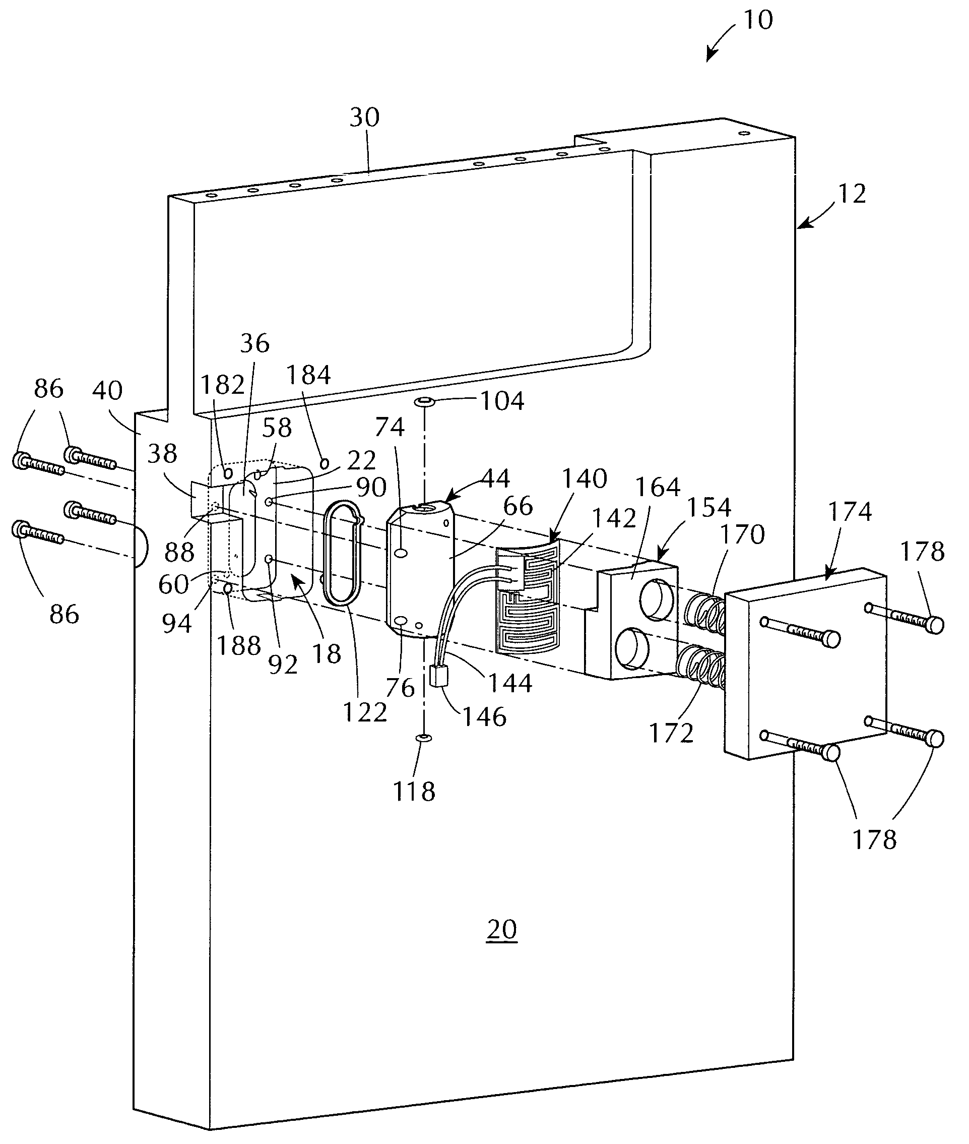
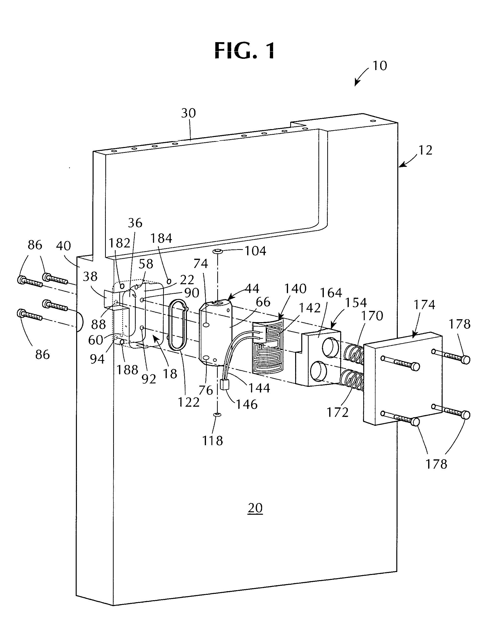
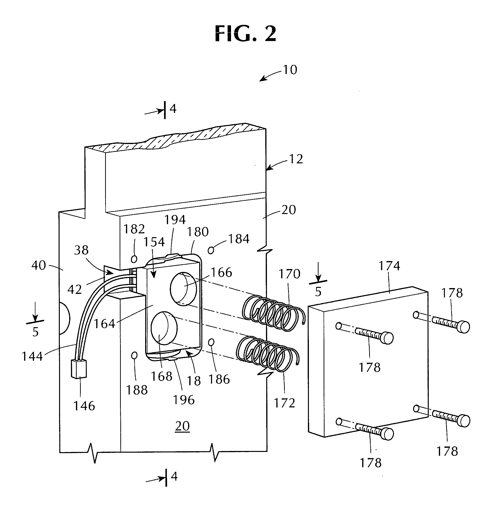
[0029] Referring to the drawings, a unified fluidics circuit of a hematology analyzer incorporating one embodiment of the invention is generally indicated by the reference number 10 in FIG. 1.

[0030] The unified fluidics circuit 10 (also referred to as the fluid circuit 10) includes a generally block-like plastic member 12 formed with a plurality of interior fluid passageways represented by circuit lines in FIG. 7. For example a fluid passageway 14 in FIG. 7 conducts fluid along a predetermined path to a reaction chamber 16 wherein fluid from the passageway 14 can be mixed and / or reacted.

[0031] The block-like plastic member 12 (also referred to as the block 12) is formed from a plurality of individual acrylic plates (not shown) that are laminated or otherwise joined together by fusion welding or other known laminating process. Each acrylic plate may include, for example, chamber recesses, valve cavity recesses and passageway recesses for pneumatic, hydraulic, and vent-lines. When t...


PUM


Abstract

The fluid circuit for a hematology analyzer includes a block-like plastic member with passageways for fluid, and a reaction chamber recess that communicates with one or more of the fluid passageways. A detachable metallic heat transfer cover member is positioned across the reaction chamber recess to close the reaction chamber recess and establish a confined reaction chamber. A heater is placed in conductive contact with the metallic heat transfer cover member to heat the cover member and thereby conduct heat to the reaction chamber. The metallic heat transfer cover member is detachably secured to the block-like plastic member and can thus be removed and replaced as needed.

Description

BACKGROUND OF THE INVENTION [0001] This invention is directed to hematology analyzers incorporating a fluidics circuit with a heated reaction chamber and more particularly to a novel fluidics circuit with a replaceable metallic heat transfer member for a heated reaction chamber. [0002] Clinical hematology analyzers are used to perform automated test analyses on body fluids, such as whole blood, to obtain data relating to the whole blood characteristics of a particular individual. The whole blood characteristics are usually compared with known acceptable whole blood parameters to determine if there are any significant deviations that might indicate a need for medical attention. [0003] For example hematology analyses can be used to detect or confirm the existence of various illnesses, diseases and infections. Thus the hematology analysis of an individual's whole blood provides information relating to their health or medical status. Such information might dictate the need for a medical...

Claims


Application Information

Patent Timeline
IPC IPC(8): B01L7/00G01N35/08G01N1/00G01N33/487G01N33/49
CPCB01L7/00Y10T436/25G01N33/49
Inventor RANERI, JOSEPH A.CARLUCCI, JOSEPH J.BEHRINGER, BRUCE E.PEETS, MICHAEL T.GOODSELL, TERRY
Owner BAYER CORP
Learn More