Variable vent diffuser

a diffuser and variable technology, applied in the direction of valve operating means/releasing devices, mechanical equipment, transportation and packaging, etc., can solve the problems of machine malfunction, device inherently inefficient, and detriment to operation

Active Publication Date: 2005-03-17
FISHER CONTROLS INT LLC
View PDF9 Cites 14 Cited by
  • Summary
  • Abstract
  • Description
  • Claims
  • Application Information

AI Technical Summary

Problems solved by technology

If not relieved, such pressure can detrimentally affect operation, lead to machine malfunction, etc.
However, such devices are inherently inefficient due to constant release or loss of pressure.
The device cannot therefore be adjusted or efficiently tailored to a dynamic environment once installed.
Furthermore, such machines generally operate under a variety of extreme conditions, such as within petroleum and chemical processing facilities, power generator plants, boilers and the like.
However, a problem with such a system is that conventional diffusers are unable to optimally perform outside a narrow range of operating conditions due to their fixed structure design.
More specifically, the fixed state of the diffuser makes optimization difficult, in that the size of the diffuser cannot be altered when the level of internal pressure or fluid flow rate changes.
Moreover, the large control valve and actuator burden those in the art with the necessity of adding such cumbersome and expensive components to the vent applications.
This requires the use of large actuators and can limit the application because of temperature concerns due to the close proximity of the actuators to the vent applications that generate and utilize pressure.

Method used


Image

  • Variable vent diffuser
  • Variable vent diffuser
  • Variable vent diffuser

Examples


Embodiment Construction

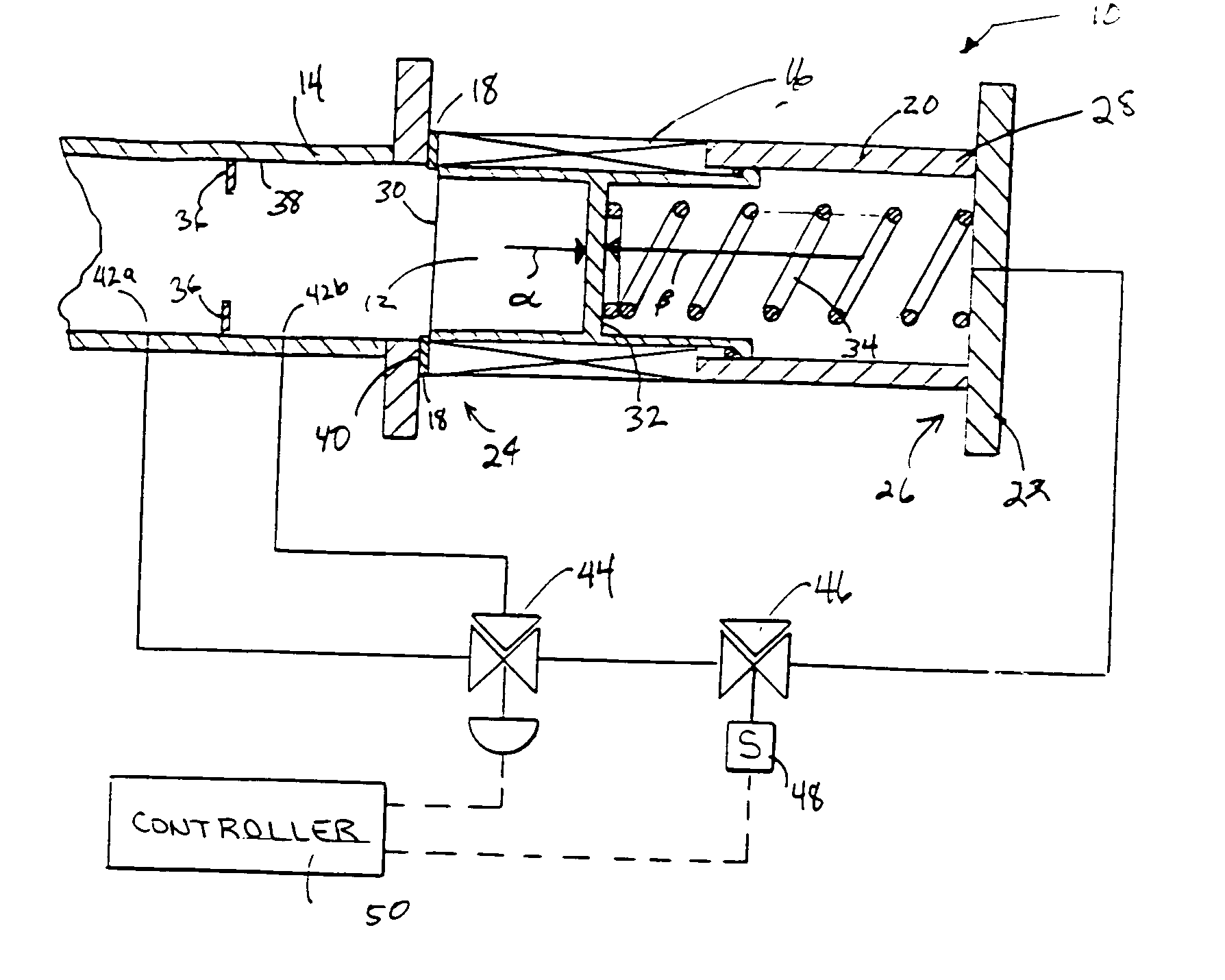
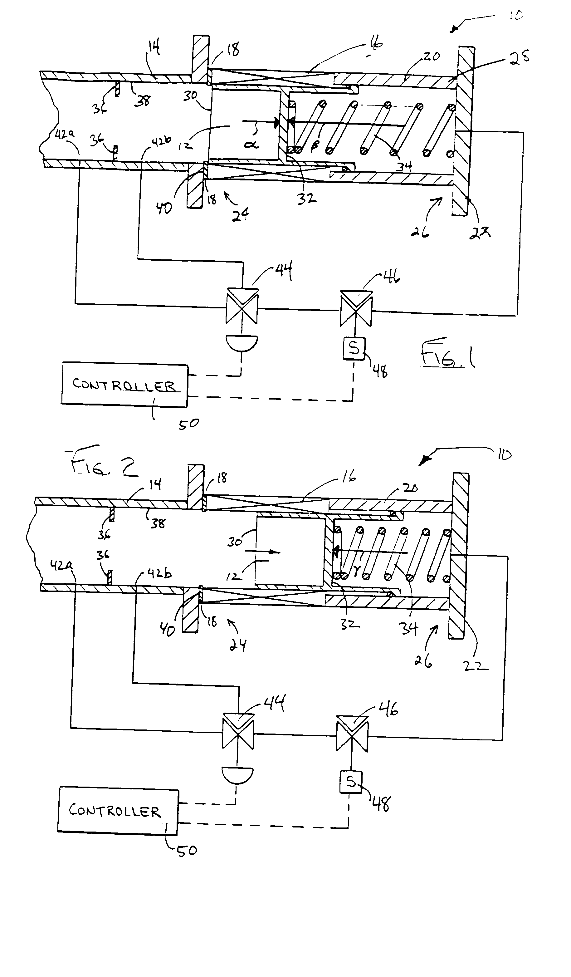
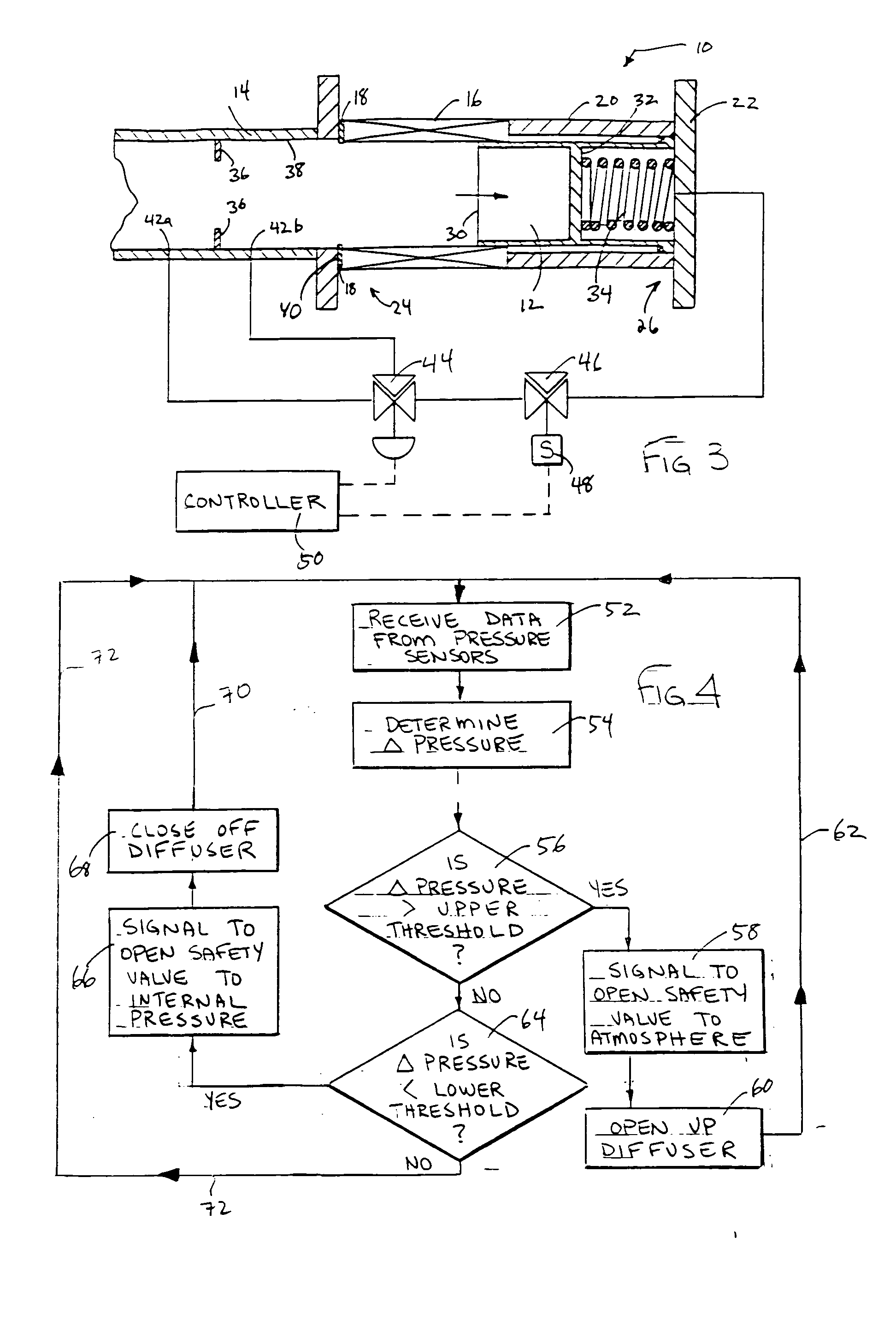
[0020] Turning now to the drawings, FIGS. 1, 2 and 3 illustrate one embodiment of a variable vent diffuser 10 which includes an adjustable plug 12 within a conduit 14, and which can assume various positions adjacent a diffuser element or aperture 16 forming part of the conduit 14. In particular, FIG. 1 illustrates this embodiment in a fully closed position, where the adjustable plug 12 is in a position that maximizes the coverage of the diffuser element 16 by the adjustable plug. FIG. 3 illustrates the same embodiment in a fully open position, where the adjustable plug 12 is in a position which maximizes the exposure of the aperture 16 to the interior space of the conduit 14. FIG. 2 illustrates the embodiment with the adjustable plug 12 in a semi-open position between fully open and fully closed positions, thereby allowing some resistance to fluid flow between the exterior and the interior space of the conduit 14 through the diffuser element 16.

[0021] In addition, the variable vent...


PUM


Abstract

A diffuser apparatus for variably controlling fluid pressure release is provided. The diffuser apparatus includes an aperture for pressure release and an adjustable plug that can variably expose the aperture by adjusting positions in response to internal pressure levels. The diffuser apparatus may also include a safety mechanism that utilizes valves to add or release pressure acting on the plug in order to open and close the aperture.

Description

FIELD OF THE DISCLOSURE [0001] The disclosure relates to diffusers and, more particularly, to vent diffusers that allow for fluid pressure release in a controlled manner. BACKGROUND OF THE DISCLOSURE [0002] Many circumstances arise in day-to-day manufacturing or processing applications that generate an excess in fluid pressure. If not relieved, such pressure can detrimentally affect operation, lead to machine malfunction, etc. Accordingly, various systems have been employed to vent excess pressure to atmosphere. Such systems can be as straightforward as an exhaust pipe or other fixed bleed orifice which constantly exhausts pressure to atmosphere. However, such devices are inherently inefficient due to constant release or loss of pressure. [0003] In still further devices, such as general pressure relief valves, excess pressure is released to atmosphere only when internal pressure reaches a set point. At the set point, the relief valve “trips”, thereby opening an orifice to atmosphere...

Claims


Application Information

Patent Timeline
Patent Type & Authority Applications(United States)
IPC IPC(8): G05D7/06G05D16/16
CPCG05D7/005Y10T137/0396Y10T137/7782Y10T137/7761
Inventor MCCARTY, MICHAEL WILDIE
Owner FISHER CONTROLS INT LLC
Why Eureka
Try Eureka