Well tool protection system and method

Inactive Publication Date: 2005-03-17
SCHLUMBERGER TECH CORP
View PDF7 Cites 19 Cited by
  • Summary
  • Abstract
  • Description
  • Claims
  • Application Information

AI Technical Summary

Benefits of technology

[0011] It may be desired for the moveable mechanism to include an operational feature of the well tool. In an embodiment of the present invention the moveable mechanism includes a slide sleeve that carries the flapper. When the slide sleeve is actuated to move downward the flapper may be moved from the closed to the open position. Utilizing the slide sleeve in functional connection with the protection fluid chamber, the protection fluid is expelled as the flapper is being opened alleviating jamming of the flapper by debris.
[0012] It has been further realized that well tools may fail when there is a pressure fluctuation in the well. The moveable mechanism spreads an uneven load across the shearing

Problems solved by technology

Well tools are operated in harsh downhole conditions often resulting in failure of the well tool to operate as intended.
One cause of the failure is due to debris that exists in the well fluid.
Another problem encountered in existing well tools is failure of a moveable mechanism to operate due to pr

Method used


Image

  • Well tool protection system and method
  • Well tool protection system and method
  • Well tool protection system and method

Examples


Embodiment Construction

[0021] Refer now to the drawings wherein depicted elements are not necessarily shown to scale and wherein like or similar elements are designated by the same reference numeral through the several views.

[0022] As used herein, the terms “up” and “down”; “upper” and “lower”; and other like terms indicating relative positions to a given point or element are utilized to more clearly describe some elements of the embodiments of the invention. Commonly, these terms relate to a reference point as the surface from which drilling operations are initiated as being the top point and the total depth of the well being the lowest point.

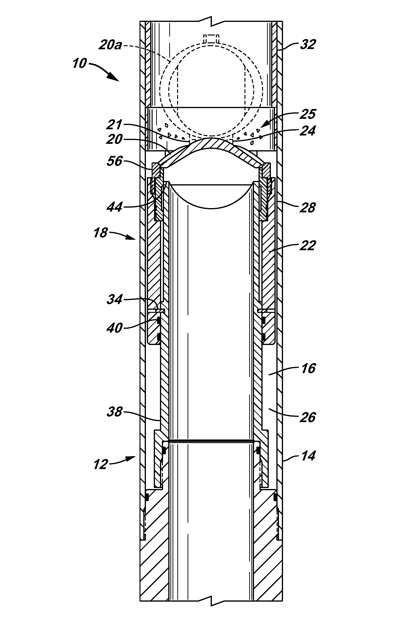
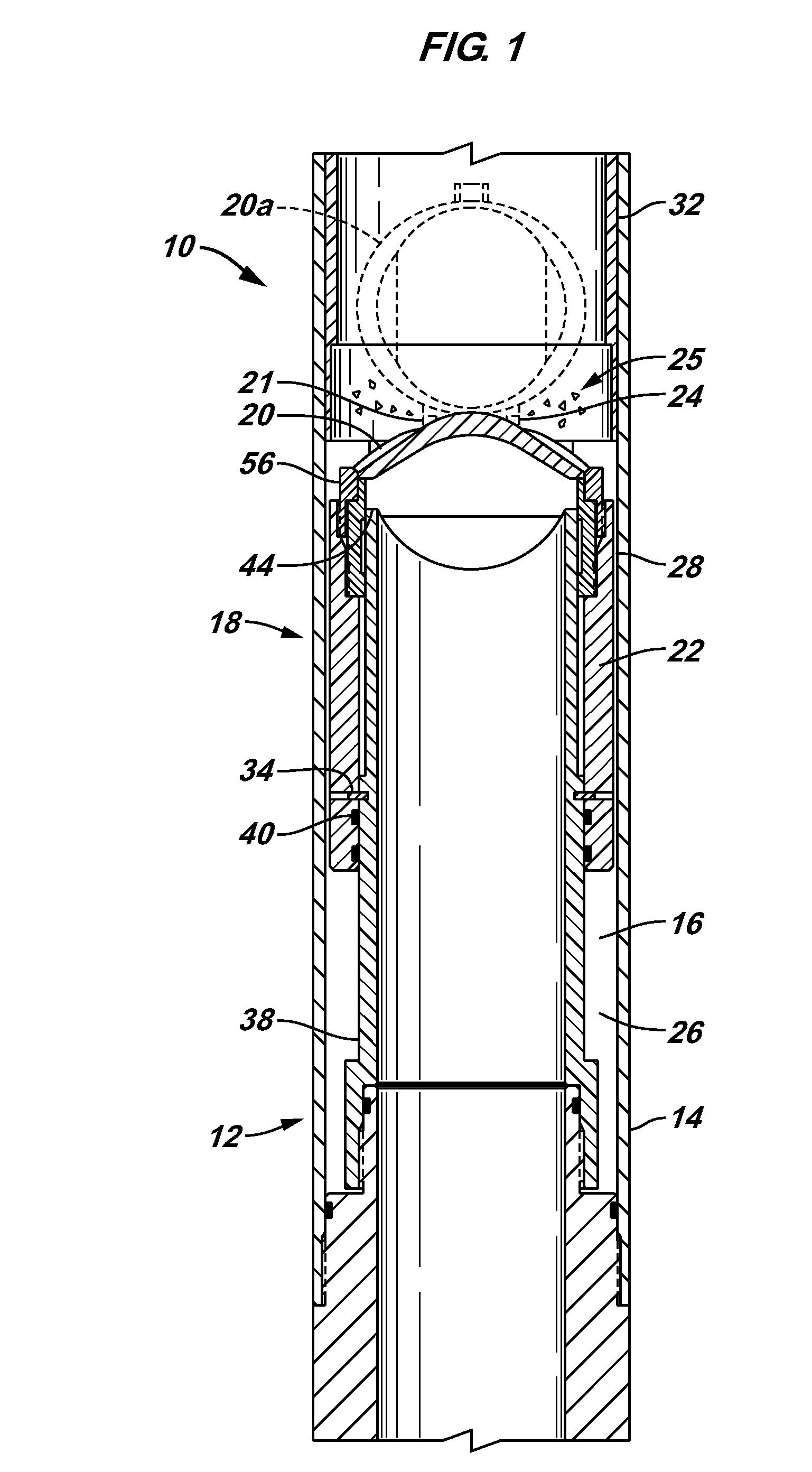
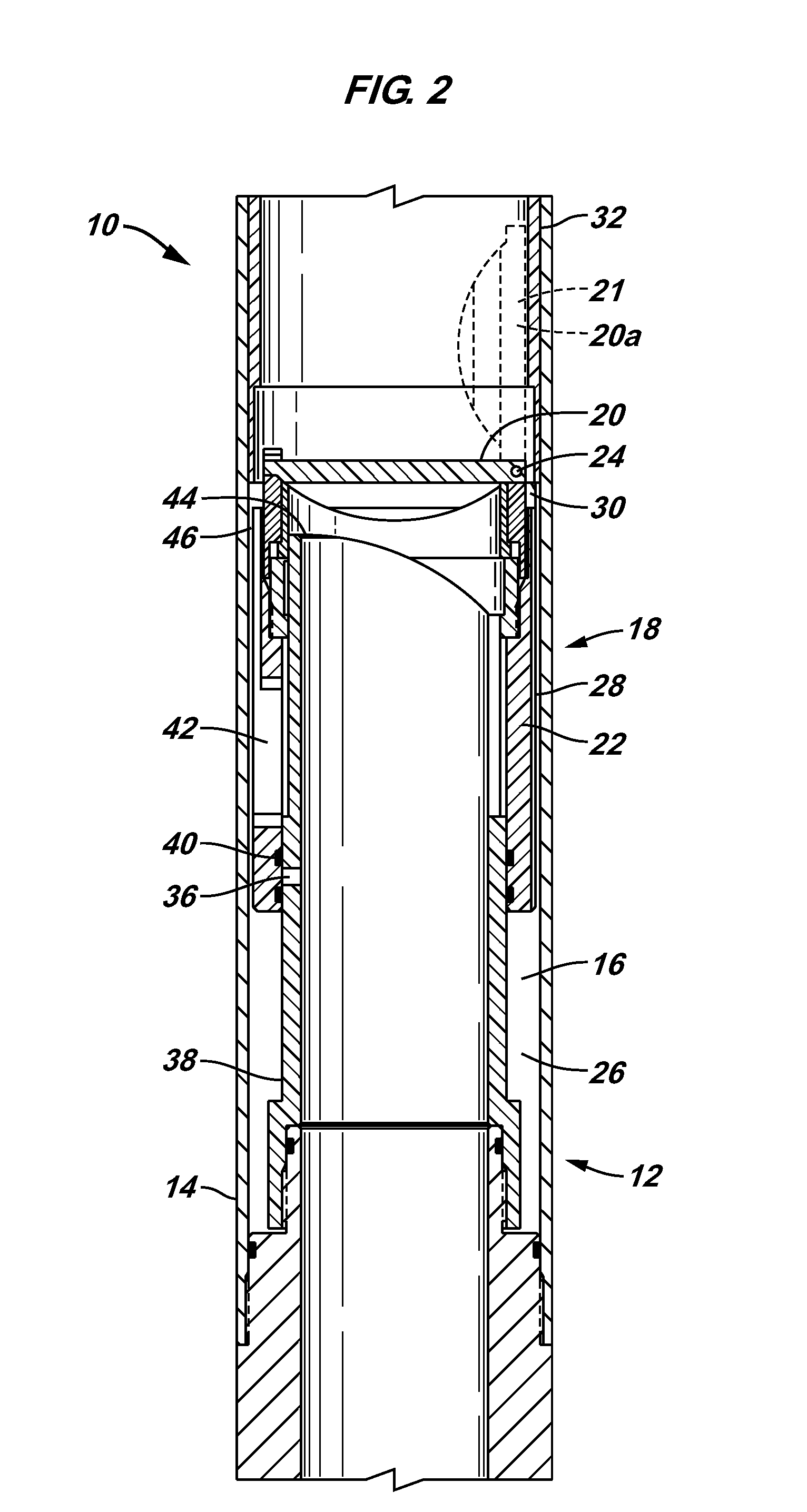
[0023]FIG. 1 is a cross-sectional view of a debris removal system of the present invention designated generally by the numeral 10. FIG. 2 is a cross-sectional view of debris removal system 10 of FIG. 1 from a different angle. With reference to FIGS. 1 and 2, debris removal system 10 includes a well tool 12 having a housing 14 carrying a protection fluid 16 and a m...


PUM


Abstract

The system including a well tool having a housing forming a protection fluid chamber in fluid communication with a discharge port, a protection fluid disposed within the protection fluid chamber, and a moveable mechanism in functional connection with the protection fluid chamber in a manner to expel a portion of the protection fluid when the moveable mechanism moves.

Description

CROSS REFERENCE TO RELATED APPLICATIONS [0001] This application claims benefit of priority from United States Provisional Application No. 60 / 503,024, filed Sep. 15, 2003 and entitled Well Tool Protection and Debris Removal, Release Mechanism, which is incorporated by reference herein.BACKGROUND OF INVENTION [0002] The present invention relates in general to well tools and more specifically to a device and method for removing debris from the vicinity of a portion of a well tool and for improved operation of the well tool. [0003] Well tools are operated in harsh downhole conditions often resulting in failure of the well tool to operate as intended. One cause of the failure is due to debris that exists in the well fluid. For example, many well tools include moveable mechanisms such as flapper type valves. These valves are positioned to be readily operated when needed. [0004] However, it is all to common for debris contained in the well fluid to settle around the flapper preventing the ...

Claims


Application Information

Patent Timeline
IPC IPC(8): E21B34/00E21B34/12E21B41/00
CPCE21B34/12E21B2034/005E21B41/00E21B2200/05E21B34/103
Inventor DU, MICHAEL HUIREAD, DENNIS M. JR.
Owner SCHLUMBERGER TECH CORP
Why Eureka
Try Eureka