Mono diameter wellbore casing

a wellbore casing, mono-diameter technology, applied in the direction of drilling pipes, wellbore/well accessories, sealing/packing, etc., can solve the problems of increased drilling rig time, increased cost, and required equipment changes, and achieve the effect of increasing the size of the adjustable expansion devi

Active Publication Date: 2005-03-17
ENVENTURE GLOBAL TECH LLC
View PDF99 Cites 147 Cited by
  • Summary
  • Abstract
  • Description
  • Claims
  • Application Information

AI Technical Summary

Benefits of technology

[0007] According to another aspect of the present invention, a method for radially expanding and plastically deforming an expandable tubular member within a borehole is provided that includes positioning an adjustable expansion device within the expandable tubular member, supporting the expandable tubular member and the adjustable expansion device within the borehole, lowering the adjustable expansion device out of the expandable tubular member, increasing the outside dimension of the adjustable expansion device, and displacing the adjustable expansion device upwardly relative to the expandable tubular member n times to radially expand and plastically deform n portions of the expandable tubular member.
[0033] According to another aspect of the present invention, a method for forming a mono diameter wellbore casing within a borehole that includes a preexisting wellbore casing is provided that includes supporting the expandable tubular member, an hydraulic actuator, and an adjustable expansion device within the borehole; increasing the size of the adjustable expansion device; displacing the adjustable expansion device upwardly relative to the expandable tubular member using the hydraulic actuator to radially expand and plastically deform a portion of the expandable tubular member; and displacing the adjustable expansion device upwardly relative to the expandable tubular member to radially expand and plastically deform the remaining portion of the expandable tubular member and a portion of the preexisting wellbore casing that overlaps with an end of the remaining portion of the expandable tubular member.

Problems solved by technology

Such a large borehole diameter involves increased costs due to heavy casing handling equipment, large drill bits and increased volumes of drilling fluid and drill cuttings.
Moreover, increased drilling rig time is involved due to required cement pumping, cement hardening, required equipment changes due to large variations in hole diameters drilled in the course of the well, and the large volume of cuttings drilled and removed.

Method used


Image

  • Mono diameter wellbore casing
  • Mono diameter wellbore casing
  • Mono diameter wellbore casing

Examples


Embodiment Construction

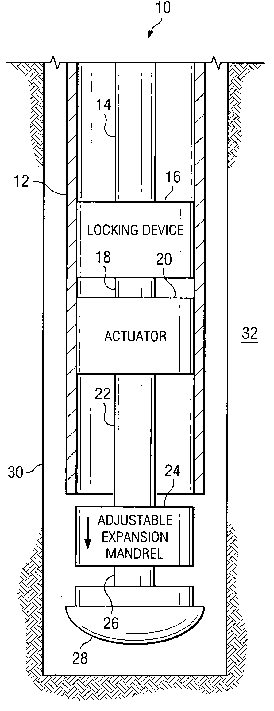
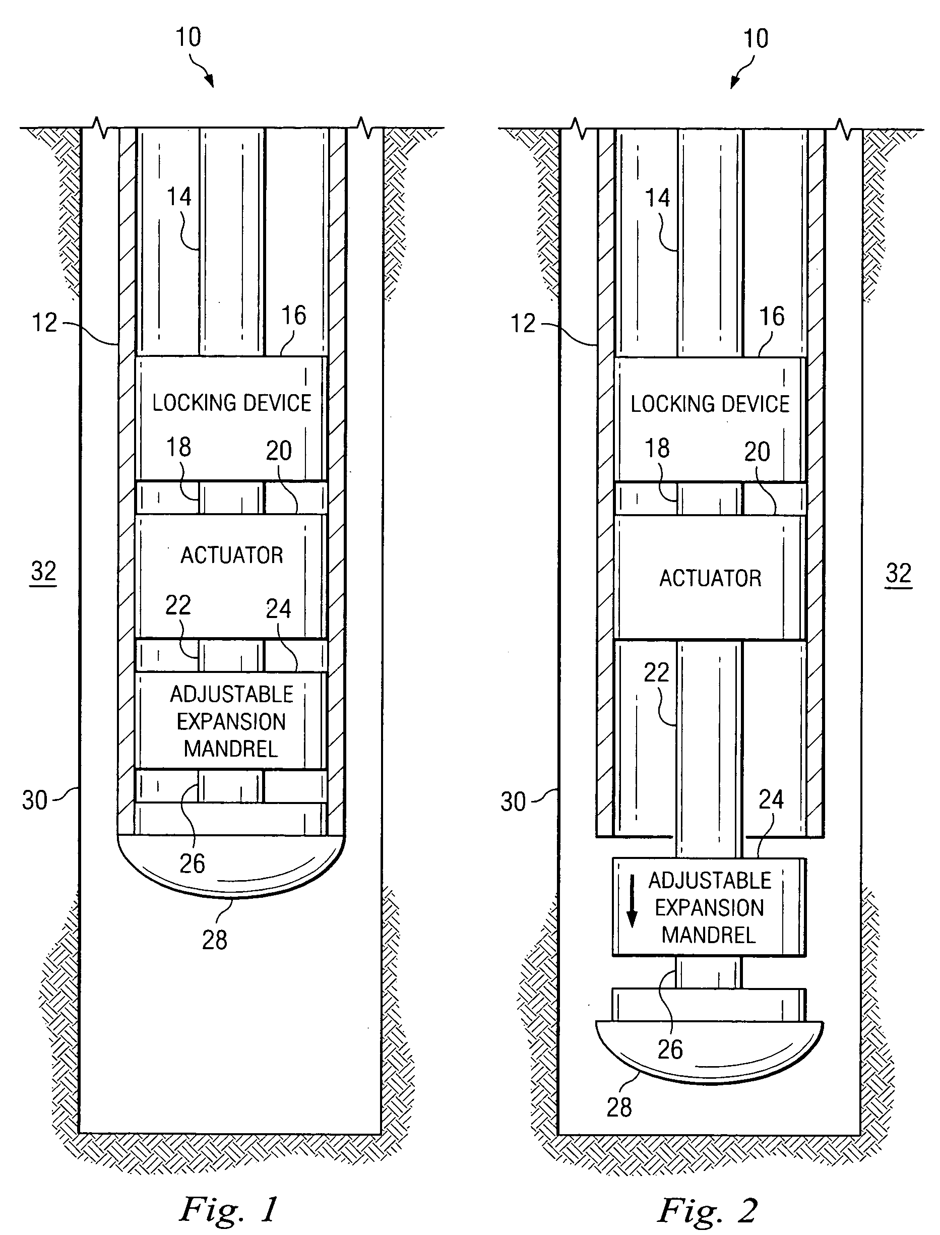
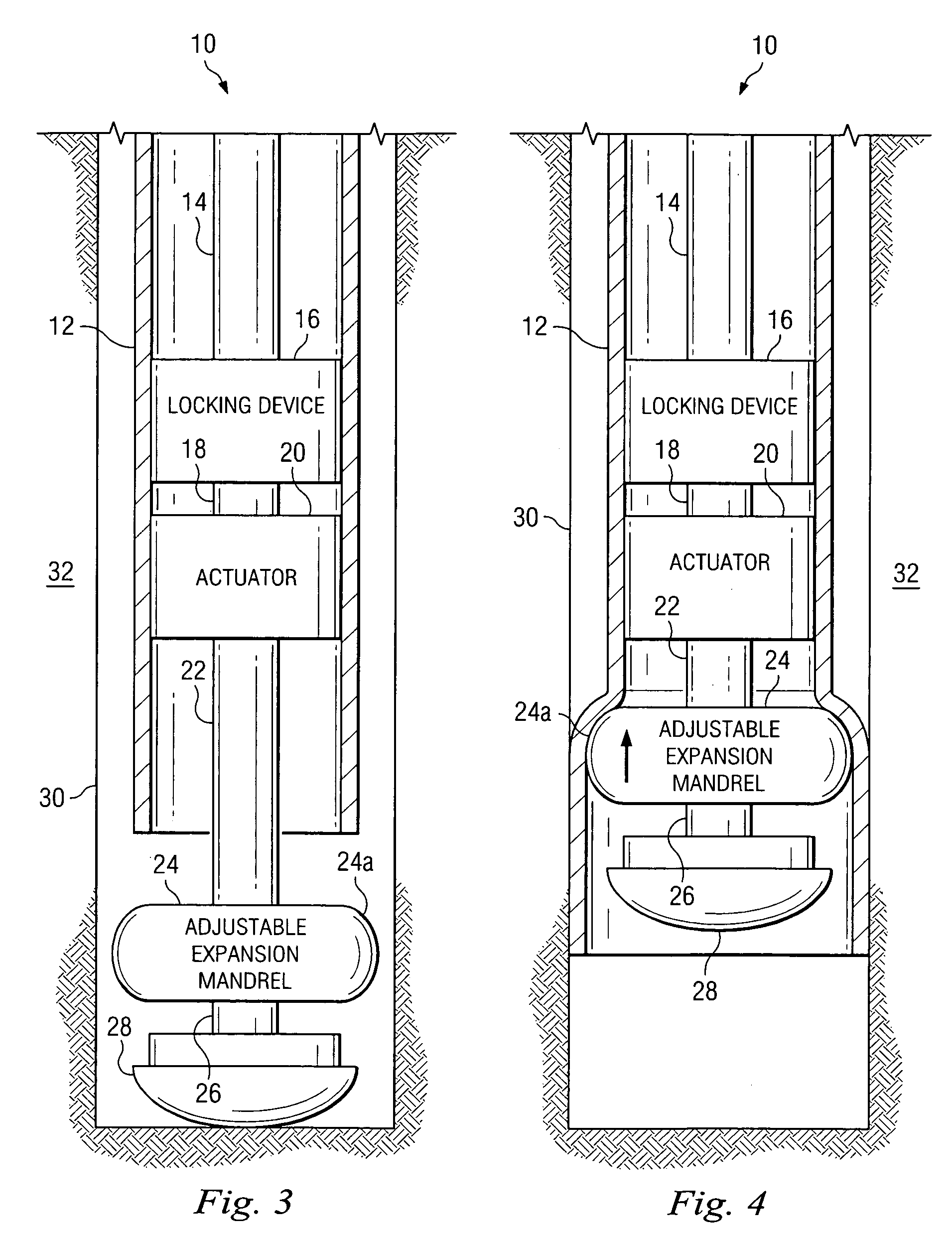
[0078] Referring to FIG. 1, an exemplary embodiment of an apparatus 10 for radially expanding and plastically deforming a tubular member 12 includes a tubular support member 14 that extends into the tubular member that is coupled to an end of a locking device 16 for controllably engaging the tubular member. Another end of the locking device 16 is coupled to a tubular support member 18 that is coupled to an end of an actuator 20. Another end of the actuator 20 is coupled to a tubular support member 22 that is coupled to an end of an adjustable expansion mandrel 24 for radially expanding and plastically deforming the tubular member 12. Another end of the adjustable expansion mandrel 24 is coupled to a tubular support member 26 that is coupled to an end of a float shoe 28 that mates with and, is at least partially received within a lower end of the tubular member 12. In an exemplary embodiment, the locking device 16, the tubular support member 18, the actuator 20, the tubular support m...


PUM


Abstract

An apparatus and method for forming a mono diameter wellbore casing.

Description

CROSS REFERENCE TO RELATED APPLICATIONS [0001] The present application is a National Stage patent application filing corresponding to PCT patent application Ser. No. PCT / US02 / 36267, attorney docket no. 25791.88.02, filed on Nov. 12, 2002, which claimed the benefit of the filing dates of: (1) U.S. provisional patent application Ser. No. 60 / 338,996, attorney docket no. 25791.87, filed on Nov. 12, 2001, (2) U.S. provisional patent application Ser. No. 60 / 339,013, attorney docket no. 88, filed on Nov. 12, 2001 (3) U.S. provisional patent application Ser. No. 60 / 363,829, attorney docket no. 25791.95, filed on Mar. 13, 2002, (4) U.S. provisional patent application Ser. No. 60 / 387,961, attorney docket no. 25791.108, filed on Jun. 12, 2002 the disclosures of which are incorporated herein by reference. [0002] The present application is related to the following: (1) U.S. patent application Ser. No. 09 / 454,139, attorney docket no. 25791.03.02, filed on Dec. 3, 1999, (2) U.S. patent application...

Claims


Application Information

Patent Timeline
Patent Type & Authority Applications(United States)
IPC IPC(8): E21BE21B7/20E21B19/00E21B23/02E21B29/00E21B43/10
CPCE21B43/105E21B43/103
Inventor RING, LEVBRISCO, DAVID PAULWATSON, BROCK WAYNEWADDELL, KEVIN K
Owner ENVENTURE GLOBAL TECH LLC
Why Eureka
Try Eureka