Power factor controller

Inactive Publication Date: 2005-03-17
PRECISIONH2
View PDF3 Cites 93 Cited by
  • Summary
  • Abstract
  • Description
  • Claims
  • Application Information

AI Technical Summary

Benefits of technology

is to eliminate the above deficiencies and provide a simple system allowing u

Problems solved by technology

These chips have important limitations that end up in incoherent system equations for calculations of the chokes and power FETs characteristics, thus requiring a lot of empirical testing from

Method used


Image

  • Power factor controller
  • Power factor controller
  • Power factor controller

Examples


Embodiment Construction

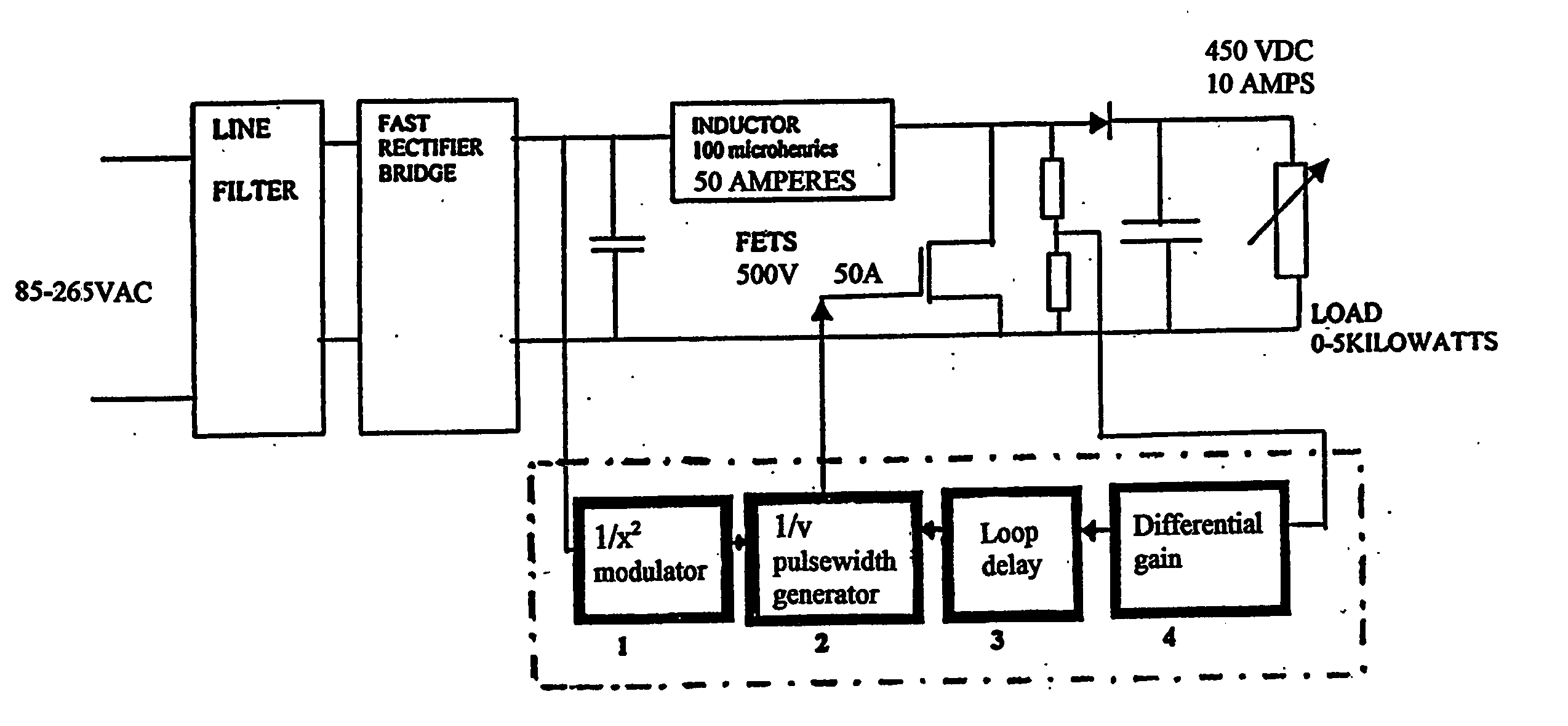
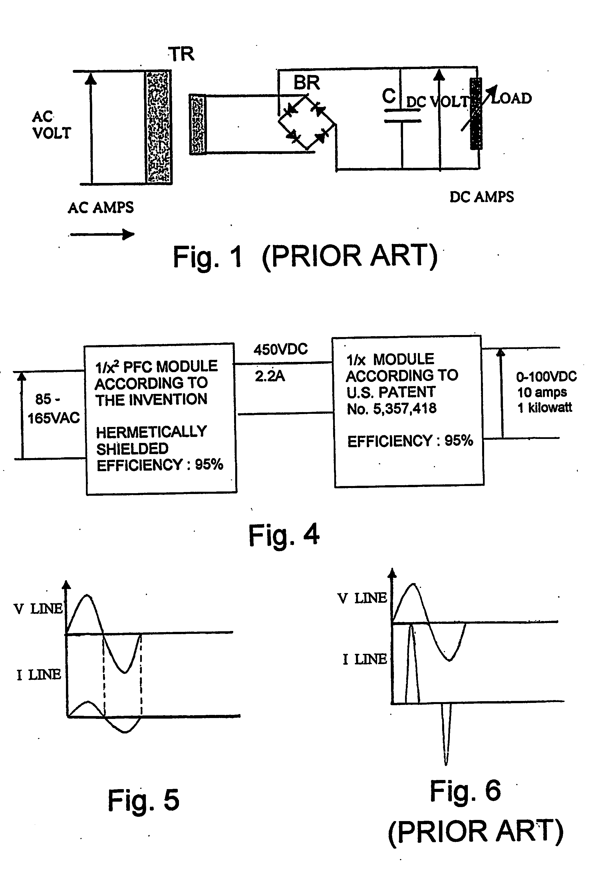
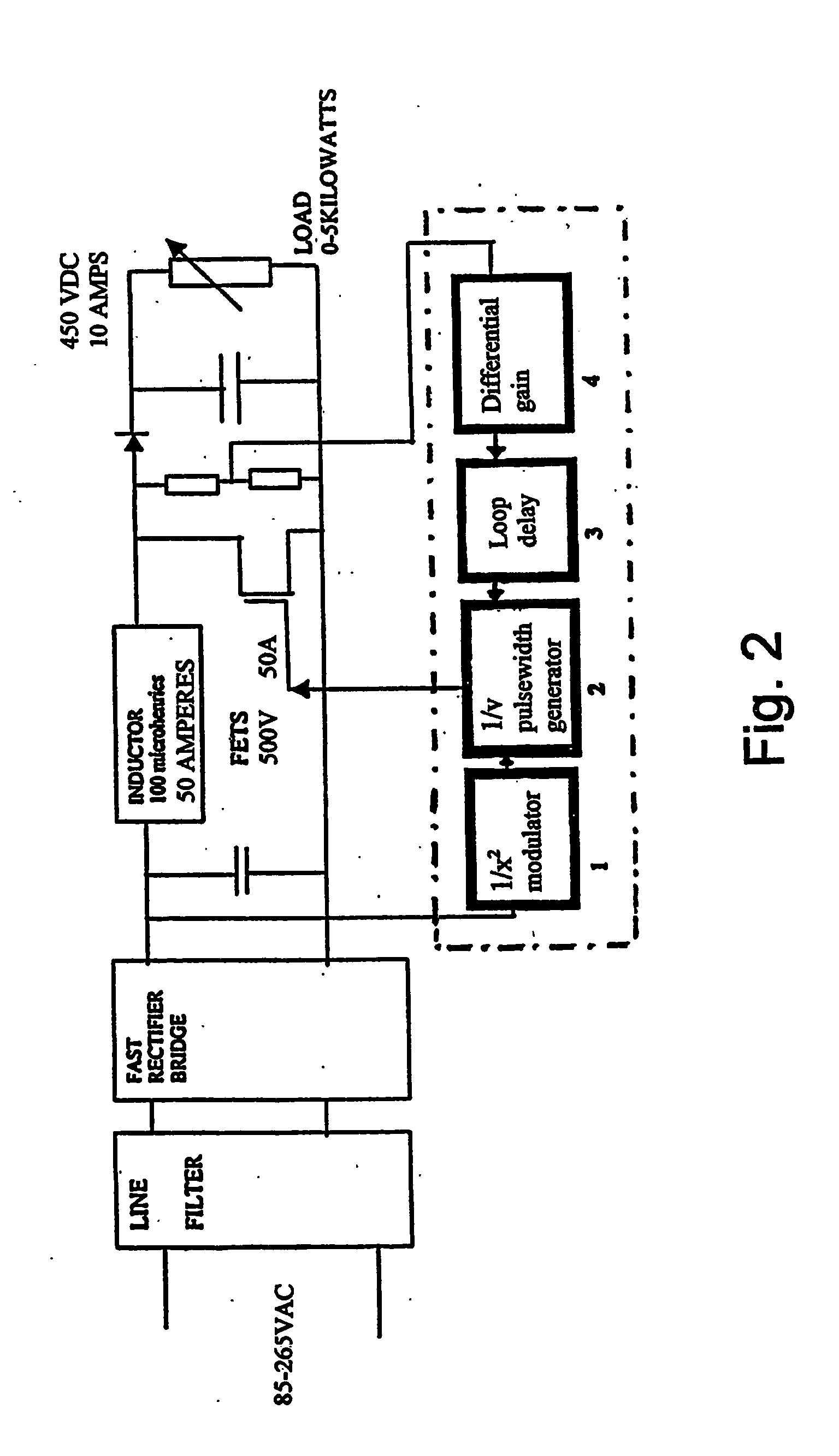
An electronic power supply can be defined as a power converter converting AC line voltage (115 VAC or 220 VAC) into a DC voltage necessary to feed any electronic circuitry. The simplest electronic power supply is shown on FIG. 1 and includes a very primitive transformer (TR), rectifying bridge (BR) of capacitor (C) type. However, such a simple arrangement is seldom used due to the following reasons: output DC voltage will change whenever the line voltage changes, thus not providing any reliable line regulation; even if the line voltage is stable, DC voltage will change if current is drawn by the load changes, thus not providing any load regulation; at 60 Hz, weight and size of transformer will become prohibitive; capacitor charging and discharging will produce a high peak current demands, i.e. harmonics of 60 Hz. Such generation of harmonics was tolerated until Jan. 1, 2001, but is no longer tolerated in Europe and soon will not be tolerated in North America.

The above deficie...


PUM


Abstract

A power factor controller or corrector is provided in a regulated power supply circuit, in which the load and line regulation circuitry is separate from one another and in which the line regulation is provided with a 1/x2 modulator in which the switching frequency is inversely proportional to the square of the line voltage.

Description

FIELD OF THE INVENTION The present invention relates to an electronic power supply and more particularly to a power factor controller or corrector (PFC). This invention is related to U.S. Pat. No. 5,357,418 issued Oct. 18, 1994 of the same inventor, which concerns a hybrid power supply with improved regulation and which is incorporated herein by reference. BACKGROUND OF THE INVENTION Presently known PFCs have the following drawbacks: They use a double feedback loop, i.e. one to sense the line current and the other to sense the output voltage. This arrangement requires heavy calculating power in the chips that generate the driving pulse width to the power FETs; These chips have important limitations that end up in incoherent system equations for calculations of the chokes and power FETs characteristics, thus requiring a lot of empirical testing from the designer or trouble shooter. Besides, it still remains unclear whether these chips are usable above 500 watts. All these factors...

Claims


Application Information

Patent Timeline
IPC IPC(8): G05F1/40H02M1/00H02M1/42
CPCY02B70/126H02M1/4225Y02B70/10
Inventor CLAVEL, ROBERT
Owner PRECISIONH2
Why Eureka
Try Eureka