Tire pressure monitoring system

Inactive Publication Date: 2005-03-17
INFINEON TECH AG
View PDF5 Cites 35 Cited by
  • Summary
  • Abstract
  • Description
  • Claims
  • Application Information

AI Technical Summary

Benefits of technology

Starting from this prior art, it is the object of the present invention to provide an improved concept for monitoring tire pressure in a tire of a vehicle, so that ov

Problems solved by technology

Due to the necessary battery operation of the sensor arrangement provided with the transmitting unit, the life of such sensor arrangements for tire pressure monitoring, however, is extremely limited.
Moreover, in the prior art there are approaches using a fixed threshold value for changes of the tire pressure sensed from the tire pressure measured values, in order to cause unconditional communication of the respective sensed tire pressure measured value from the transmitting unit of the tire pressure sensor arrangement to an external receiving unit arranged for this, wherein the receiving unit is usually connected to vehicle electronics in order to make the sensed tire pressure measured values available to the driver via an on-board computer.
With the previously known battery-operated tire pressure sensor arrangements it is not possible to make continuous measurements of th

Method used


Image

  • Tire pressure monitoring system
  • Tire pressure monitoring system
  • Tire pressure monitoring system

Examples


Embodiment Construction

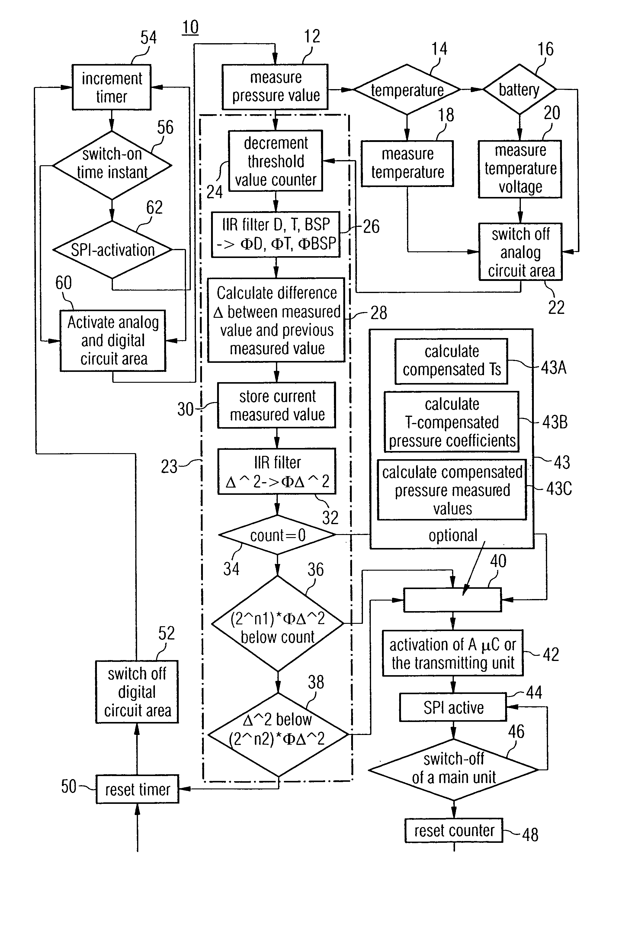
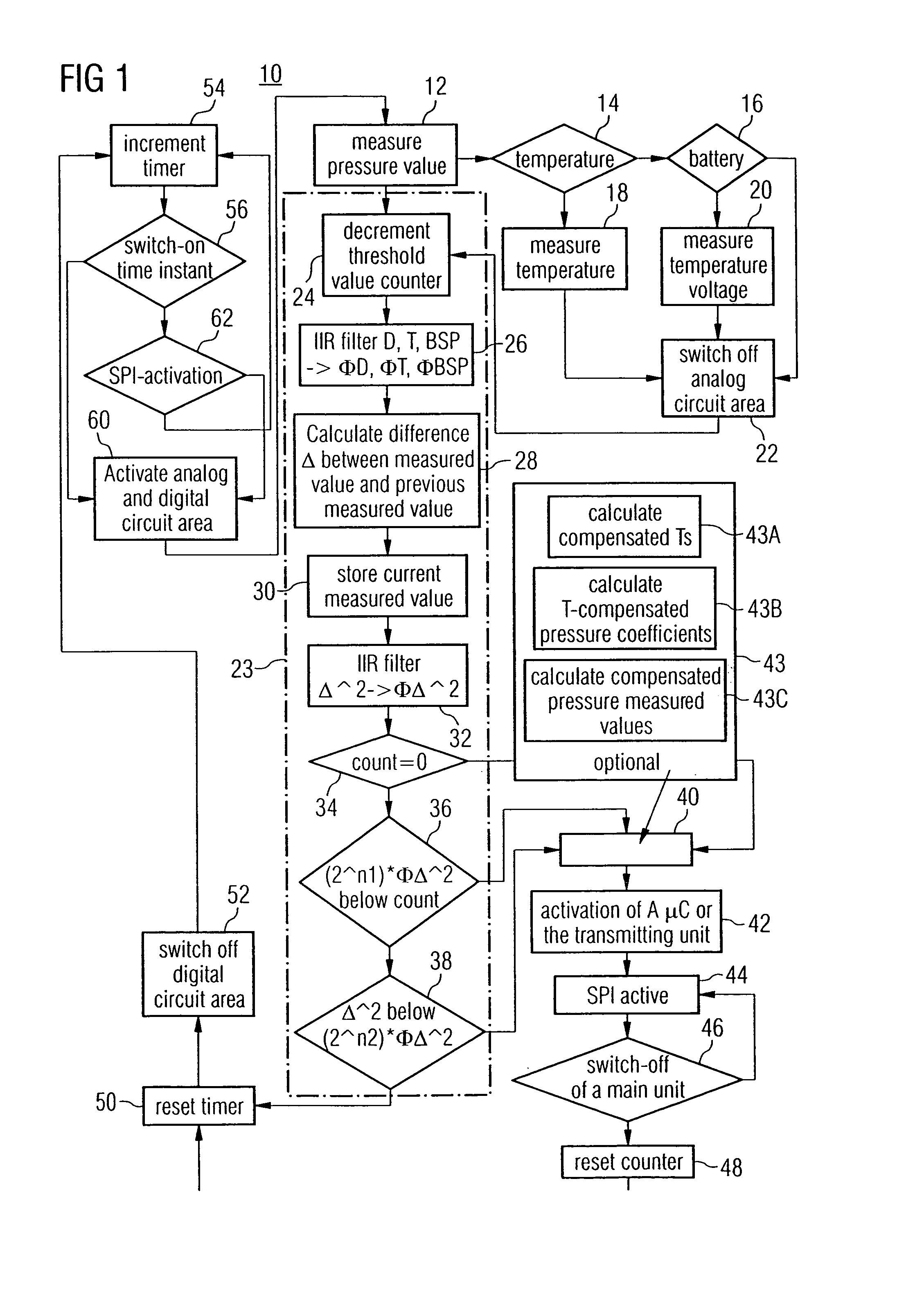
With reference to FIG. 1, now a preferred embodiment of the present invention for the monitoring of tire pressure in a vehicle tire will be discussed on the basis of a flow chart.

As shown in box 12 of the flow chart 10 of FIG. 1, the method of monitoring tire pressure in a vehicle tire begins with sensing temporally successive tire pressure measured values. Furthermore, as shown in boxes 14 and 16 of flow chart 10, in addition optionally the temperature of the tire or the gas temperature in the tire and the battery state, i.e. the battery voltage are sensed. The values are then provided along with the current tire pressure measured value as temperature measured value and battery voltage measured value, as this is illustrated in boxes 18 and 20 of flow chart 10. After the physical state quantities of the vehicle tire have been sensed and the battery voltage has been ascertained, the power supply for the measuring means is switched off, as this is illustrated in box 22 (power down ...


PUM


Abstract

In the system for monitoring tire pressure in a tire of a vehicle, temporally successive tire pressure measured values are sensed by a transmitting unit, and at least part of the tire pressure measured values is transmitted to a receiving unit with a variable frequency of occurrence, wherein the frequency of occurrence is derived from the sensed tire pressure measured values by means of a control unit.

Description

TECHNICAL FIELD OF THE INVENTION The present invention relates to a pressure sensor system, and in particular to a system for monitoring tire pressure in a vehicle tire. DESCRIPTION OF THE RELATED ART In vehicle technology, greater and greater efforts are made to develop tire pressure sensor systems with which the tire pressure of a motor vehicle, e.g. a truck, car, or motorbike may be sensed. By means of such tire pressure sensor systems, pressure changes are to be passed to a central unit, e.g. the on-board computer of the vehicle, as early as possible in order to thus recognize damage of a tire as early as possible or warn the driver sufficiently early when tire pressure changes are present, because these indicate gas loss or abnormal deformation of the tire. With this, the driver of a motor vehicle may often still be warned sufficiently early of the bursting of a vehicle tire due to damage or also of a so-called “slow flat”. For the measurement and monitoring of physical stat...

Claims


Application Information

Patent Timeline
IPC IPC(8): B60C23/04
CPCB60C23/0408B60C23/0474
Inventor HAMMERSCHMIDT, DIRK
Owner INFINEON TECH AG
Why Eureka
Try Eureka