Continuous wave (CW) - fixed multiple frequency triggered, radio frequency identification (RFID) tag and system and method employing same

a technology of continuous wave and fixed multiple frequency, applied in the field of rfid tags and systems employing same, can solve the problems of high cost, relatively complex circuits, and general limited range of systems

Inactive Publication Date: 2005-03-17
THE UNITED STATES OF AMERICA AS REPRESENTED BY THE SECRETARY OF THE NAVY
View PDF15 Cites 37 Cited by
  • Summary
  • Abstract
  • Description
  • Claims
  • Application Information

AI Technical Summary

Benefits of technology

[0013] According to a further aspect, the present invention provides a far field radio frequency identification (RFID) tagging and tracking system employing a plurality of continuous wave (CW), unmodulated signals selected from frequencies including a predetermined frequency band, the system including a RFID interrogator generating a group of CW unmodulated signals corresponding to a RFID tag and receiving a tag identification (ID) signal sequence uniquely identifying the RFID tag, and the RFID tag including a power source supplying power to the RFID tag but not including a microprocessor. If desired, the RFID tagging and tracking system includes a RFID interrogator and at least one RFID tag. The RFID interrogator includes first and second antennas, a front end coupled to the first antenna that extracts the tag ID signal sequence from a received signal, a controller receiving the tag ID signal sequence and generating control signals, a multiple frequency generator generating a plurality of CW unmodulated frequency signals, a switch array responsive to the control signals that route selected ones of the CW unmodulated frequency signals to a frequency summer, and the frequency summer, which applies the selected ones of the CW unmodulated frequency signals to the second antenna. Moreover, the RFID tag includes a third antenna generating received CW signals responsive to the selected ones of the CW unmodulated frequency signals output by the second antenna, a filter bank generating noise-free CW signals responsive to the received CW signals, a rectifier bank generating a binary word responsive to the noise-reduced CW signals, a logic circuit generating a command signal when the received binary word corresponds to a tag identifier code programmed into the logic circuit, and a state machine coupled to the third antenna and responsive to the command signal generating the tag ID signal sequence for transmission via the third antenna to the RFID interrogator. It should be noted that the first antenna could include a directional antenna, which permits the controller to determine a bearing line to the RFID tag. In any event, the controller provides a data storage function and a display function.

Problems solved by technology

It will be appreciated that these systems generally have very limited range.
These circuits are fairly complex and expensive due to the use of microprocessors.

Method used


Image

  • Continuous wave (CW) - fixed multiple frequency triggered, radio frequency identification (RFID) tag and system and method employing same
  • Continuous wave (CW) - fixed multiple frequency triggered, radio frequency identification (RFID) tag and system and method employing same
  • Continuous wave (CW) - fixed multiple frequency triggered, radio frequency identification (RFID) tag and system and method employing same

Examples


Embodiment Construction

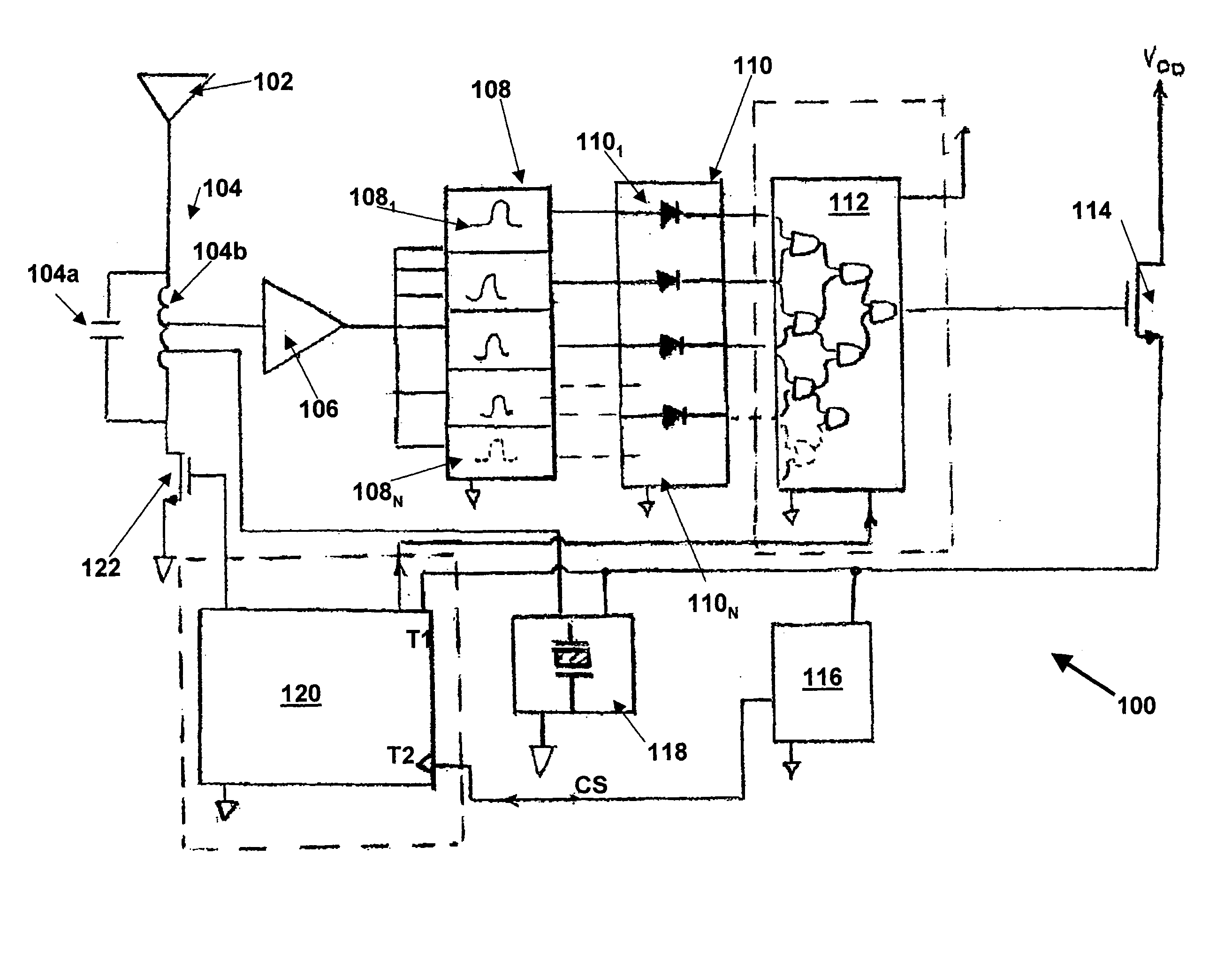
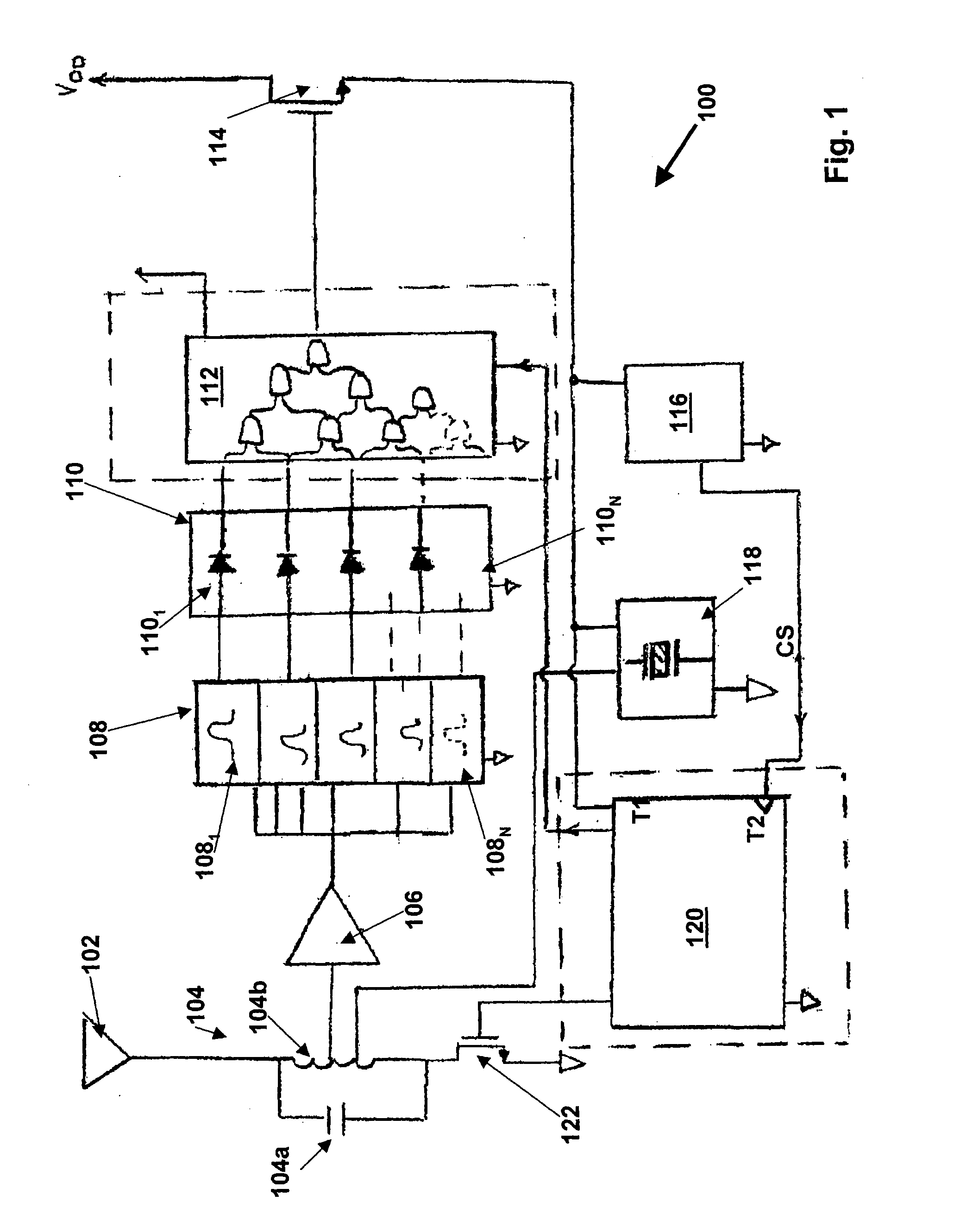
[0021] As mentioned above, the far field radio frequency identification (RFID) tagging and tracking system according to the present invention includes low cost RFID tags that can respond to queries from a RFID interrotator without producing undesirable data collision. It will be appreciated that this operational characteristic of the RFID tags stems from the fact that only one of the RFID tags will “wake-up” and respond to a particular fixed frequency trigger signal generated by the RFID interrogator. It will also be appreciated that the RFID tagging and tracking system advantageously can be utilized in the tracking of inventory and assets for a wide range of applications including but not limited to inventory data collection in a warehouse system, tracking of mobile assets, e.g., tanks, trucks, etc., and security monitoring of personnel.

[0022] In the far field RFID tagging and tracking system according to the present invention, the interrogator alone contains all complex component...


PUM


Abstract

A far field radio frequency identification (RFID) tagging and tracking system employing a plurality of continuous wave (CW), unmodulated signals selected from frequencies including a predetermined frequency band, includes a RFID interrogator generating a group of CW unmodulated signals corresponding to a RFID tag and receiving a tag identification (ID) signal sequence uniquely identifying the RFID tag, while the RFID tag includes a power source supplying power to the RFID tag but not including a microprocessor. A corresponding RFID tag and method for operating both the tag and the system are also described.

Description

STATEMENT OF GOVERNMENT INTEREST [0001] The invention described herein may be manufactured and used by or for the Government of the United States of America for governmental purposes without the payment of any royalties thereon or therefor. BACKGROUND OF THE INVENTION [0002] The present invention relates generally to a Radio Frequency Identification (RFID) tags and systems employing same. More specifically, the invention relates to a RFID tag and corresponding system employing same triggered by a fixed multiple frequency signal. A method for operating the RFID tag is also disclosed. [0003] Radio Frequency Identification (RFID) is becoming an important identification technology in applications such as inventory management, security access, personnel identification, factory automation, automotive toll debiting, and vehicle identification, to name just a few. RFID systems utilize an RFID transmitter-receiver unit (usually referred to as a base station or interrogator) to query an RFID ...

Claims


Application Information

Patent Timeline
Patent Type & Authority Applications(United States)
IPC IPC(8): G06K7/00G06K19/067G06K19/07
CPCG06K7/0008G06K19/0723G06K19/067G06K7/10069
Inventor CORBETT, BLAISE L.WORKMAN, MICHAEL L.
Owner THE UNITED STATES OF AMERICA AS REPRESENTED BY THE SECRETARY OF THE NAVY
Why Eureka
Try Eureka