
Gate antenna device

a technology of antenna device and gate, which is applied in the direction of loop antenna, individually energised antenna array, instruments, etc., can solve the problems of power consumption increase, phase shift of reception signal, and restriction of the use of an antenna that supplies high power in excess of the limi

Inactive Publication Date: 2005-03-17
PANASONIC CORP
View PDF24 Cites 71 Cited by
  • Summary
  • Abstract
  • Description
  • Claims
  • Application Information

AI Technical Summary

Benefits of technology

[0010] The invention solves the above-described problems, and it is an object of the invention to provide a gate antenna device which is preferably used with an IC-integrated media reader or IC-integrated media reader / writer to allow a reduction in transmitting power and increases in a communication distance and a communication range, to prevent any null point in a communication range, and to allow a reduction in the strength of a leakage electric field.

Problems solved by technology

JP-A-2003-258545, a problem has arisen in that power consumption increases and in that correction of phase shifts of a reception signal on the different antennas is required especially in communicating with a radio communication medium for mutual data communication.
However, the strength of a leakage electric field from induction-type read / write communication facility is limited to a distance of 10 meters by the Radio Law, and the use of an antenna that supplies high power in the excess of the limit is restricted.
An increase in the level of power fed to an antenna results in a reduction of a communication range, which has led to a problem that communication with an IC-integrated medium becomes unsatisfactory.
When a multiplicity of antennas is provided, however, a problem arises in that there will be a corresponding increase in power consumption, and this is disadvantageous for construction of a system for which low power consumption is desired.

Method used


Image

  • Gate antenna device
  • Gate antenna device
  • Gate antenna device

Examples


embodiment 1

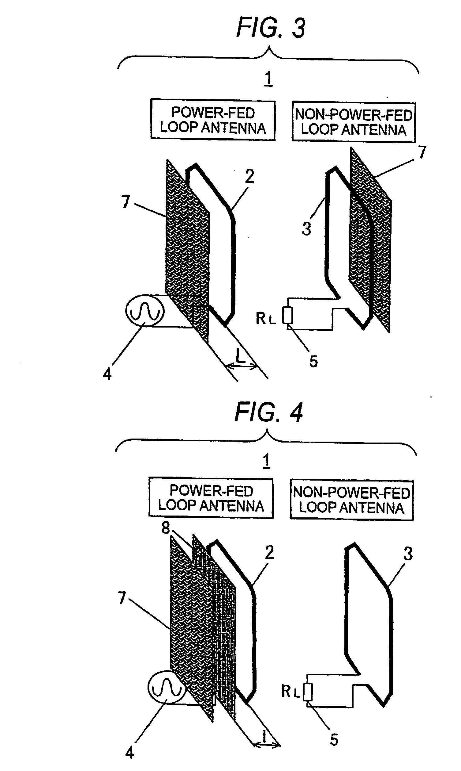
[0035]FIGS. 1, 2, 3, 4, 5, 6, 7, and 8 are configuration diagrams of a gate antenna device according to Embodiment 1 of the invention.

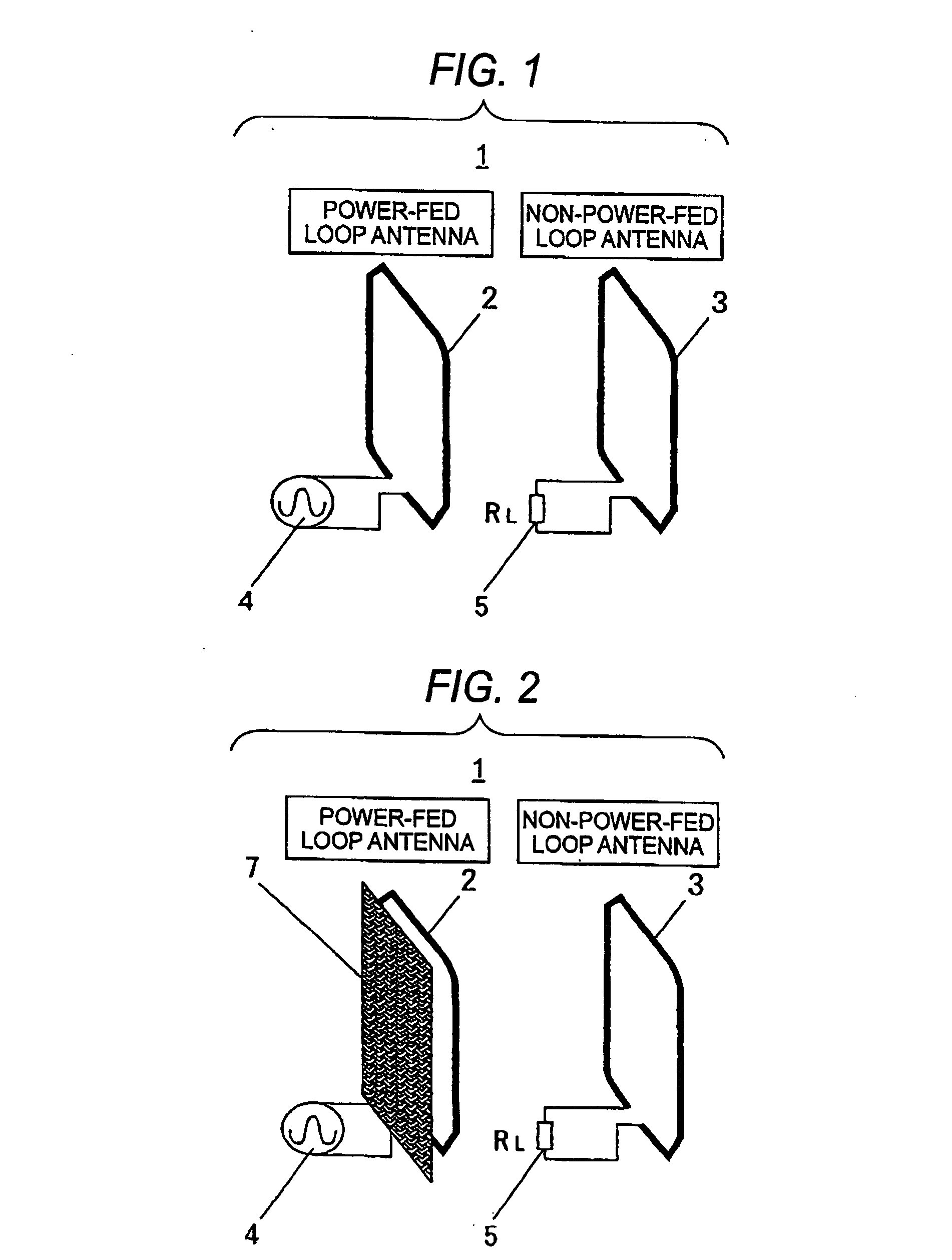
[0036] Reference numeral 1 represents a gate antenna device; reference numeral 2 represents a power-fed loop antenna; reference numeral 3 represents a non-power-fed loop antenna; reference numeral 4 represents a feeding unit; reference number 5 represents a terminating resistance; reference numeral 7 represents an electromagnetic wave leakage prevention plate; reference numeral 8 represents a magnetic plate; reference numeral 9 represents a resonance circuit; and reference numeral 10 represents a matching circuit.

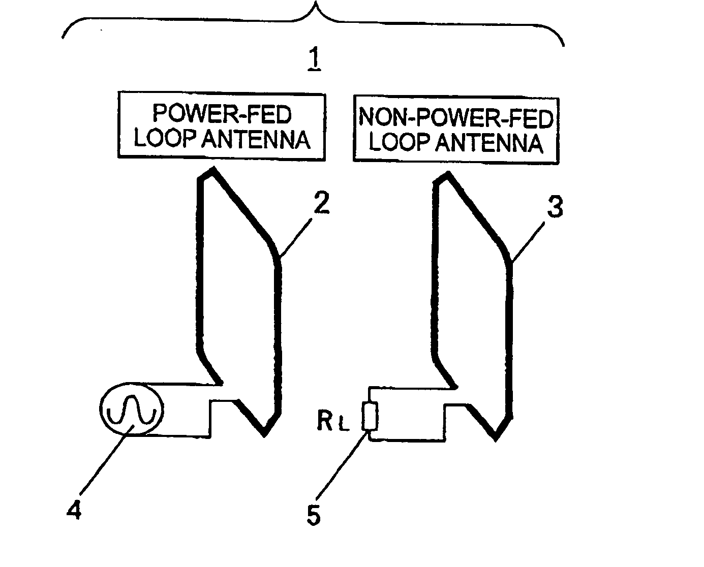
[0037] First, a basic configuration of the gate antenna device 1 will be described with reference to FIG. 1.

[0038] Each of the power-fed loop antenna 2 and the non-power-fed loop antenna 3 may be a loop antenna which has an opening in the middle thereof and whose number of turns is one or more. The power-fed loop antenna 2 and the non-powe...

embodiment 2

[0066]FIGS. 9, 10, 11, and 12 are configuration diagrams of a gate antenna device according to Embodiment 2 of the invention.

[0067] Reference numeral 15 represents a gate antenna device, and reference numeral 16 represents a loop antenna set. The loop antenna set 16 is an antenna set constituted by a combination of a power-fed loop antenna 2 and a non-power-fed loop antenna 3. As shown in FIG. 9, a three-dimensional space is represented by three axes, i.e., X, Y, and Z axes, and a loop antenna set 16 is provided on each of four planes defined by the X and Y axes. Specifically, a line drawn substantially vertically to the X-Y plane or drawn along the Z axis is laterally surrounded. The loop antenna sets 16 provided on the four lateral planes surrounding the line are disposed such that they cross each other at a crossing angle of about 90 deg. That is, they may be disposed in the form of a square or rectangle when viewed in the direction of the Z axis. Alternatively, they may be disp...

embodiment 3

[0086]FIG. 13 is a configuration diagram of an IC-integrated media reader / writer according to Embodiment 3 of the invention.

[0087] Reference numeral 30 represents an IC-integrated media reader / writer; reference numeral 31 represents a gate antenna device; reference numeral 32 represents a power-fed loop antenna; reference numeral 33 represents a non-power-fed loop antenna; reference numeral 34 represents a reader / writer apparatus; reference numeral 35 represents a display; and reference numeral 36 represents an IC-integrated medium. The IC-integrated media reader / writer 30 may perform reading from the IC-integrated medium 36 only or may perform also writing of the IC-integrated medium 36. An operation of demodulating a signal received from the IC-integrated medium 36 may be performed in the former case, and a modulated signal may be transmitted to write it in the IC-integrated medium 36 in the latter case.

[0088] The IC-integrated medium 36 passes through a region sandwiched by the...


PUM


Abstract

The invention is aimed at providing a gate antenna device which expands the distance and range of communication with an IC-integrated medium and improves the accuracy of communication while suppressing power consumption and leakage electric fields. A gate antenna device having a plurality of loop antennas which supplies power and transmission data to an IC-integrated medium through electromagnetic induction and acquires reception data in the form of a fluctuation of a load from the IC-integrated medium. The plurality of loop antennas include a power-fed loop antenna to which a signal current is supplied and a non-power-fed loop antenna to which no signal current is supplied.

Description

BACKGROUND OF THE INVENTION [0001] 1. Field of the Invention [0002] It is an object of the present invention to provide a gate type antenna device which is preferably used in an IC-integrated media reader or reader / writer for supplying power and transmission data to an IC-integrated medium, e.g., a non-contact IC card and acquiring reception data in the form of load fluctuations from the non-contact IC card. [0003] 2. Description of the Related Art [0004] For purposes such as authentication and sorting of destinations of baggage, it is becoming common to use IC-integrated media having ID codes such as IC cards and IC tags and IC-integrated media readers and IC-integrated media readers / writers for authenticating ID codes of such IC-integrated media. When an IC-integrated medium enters a communication range of an antenna of an IC-integrated media reader, an electromagnetic wave from the antenna generates an induction voltage at an antenna of the IC-integrated medium, and the voltage i...

Claims


Application Information

Patent Timeline
IPC IPC(8): G06K17/00G06K7/08H01Q1/22H01Q1/52H01Q7/00H01Q19/00H01Q19/10H01Q21/06
CPCG06K7/10178G06K7/10336H01Q19/005H01Q1/2216H01Q7/00H01Q1/22
Inventor DEGUCHI, FUTOSHIYOSHINAGA, HIROSHITANAKA, MASAHIKOHARUYAMA, HIROAKI
Owner PANASONIC CORP
Features
  • Generate Ideas
  • Intellectual Property
  • Life Sciences
  • Materials
  • Tech Scout
  • Unparalleled Data Quality
  • Higher Quality Content
  • 60% Fewer Hallucinations
Learn More