
Screen having a touch-sensitive user interface for command input

Inactive Publication Date: 2005-03-17
SIEMENS AG
View PDF5 Cites 434 Cited by
  • Summary
  • Abstract
  • Description
  • Claims
  • Application Information

AI Technical Summary

Benefits of technology

[0006] It is therefore an object of the invention to provide a screen which gives the user a perceptible acknowledgement about a successful command input even when the screen is not being or cannot be looked at.
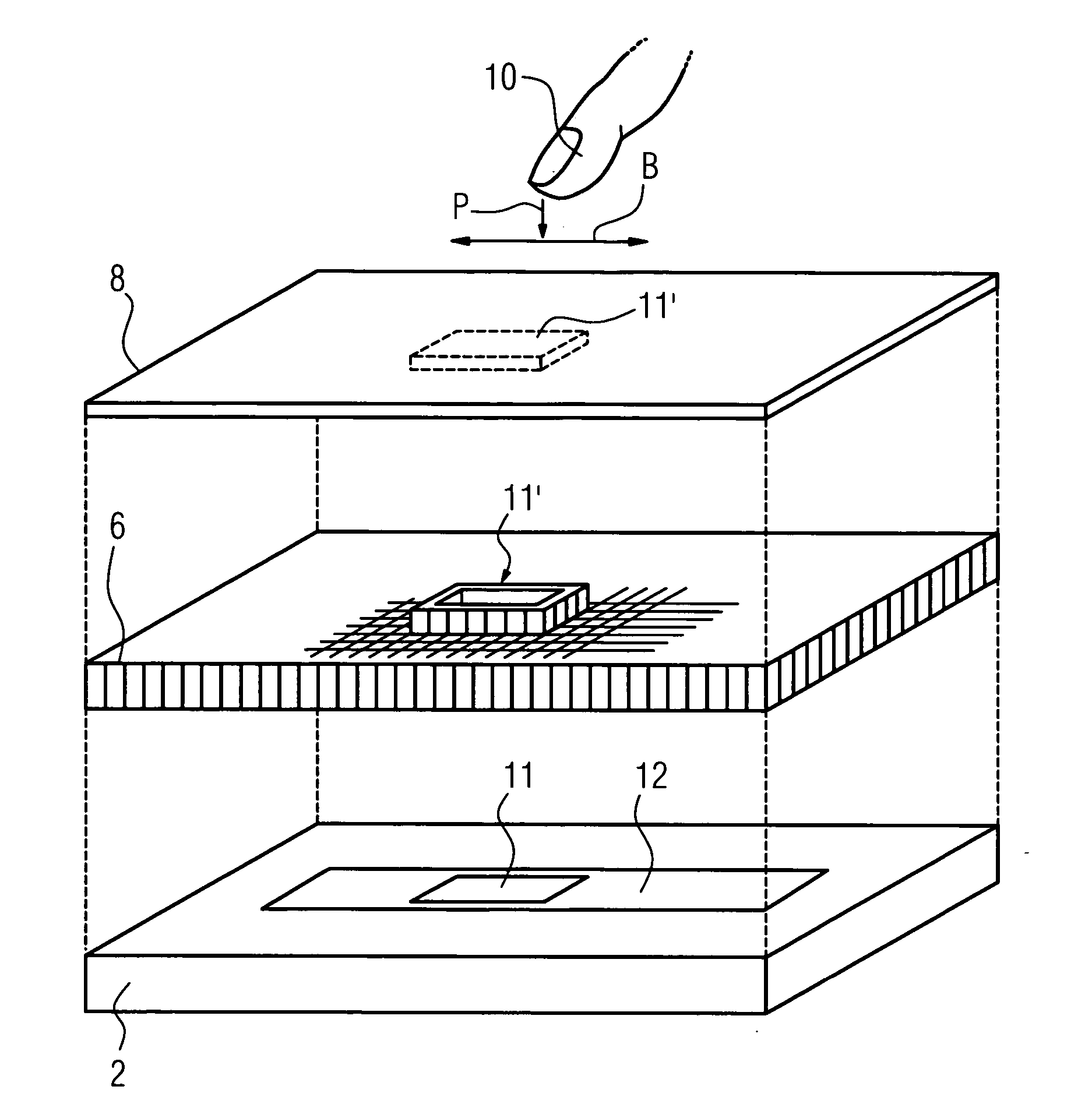
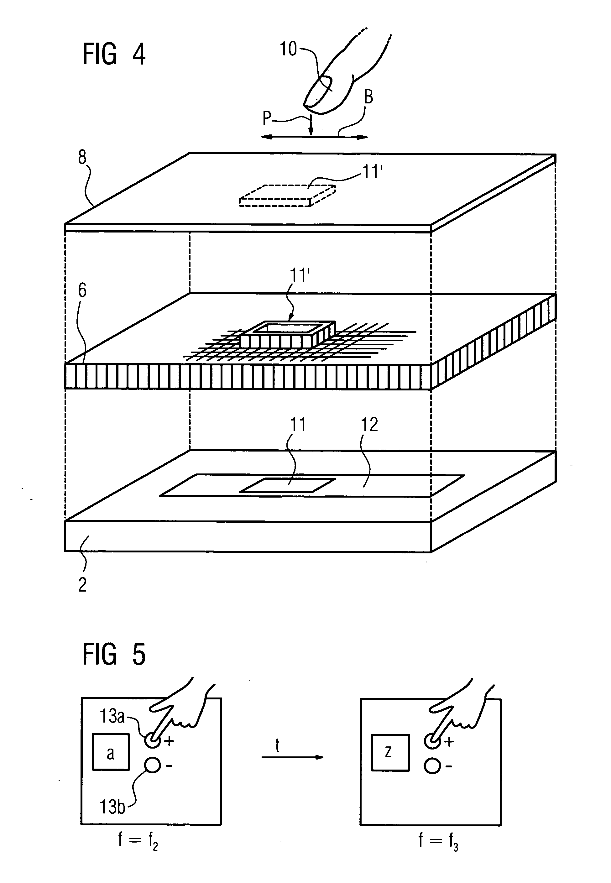
[0015] As has already been disclosed above, it is possible for control elements to be displayed three-dimensionally using the three-dimensionally deformable and electrically actuatable means such as the piezoelectric layer. In the above case, a display using input keys or “buttons” should be considered in the first instance. It is also possible, however, to display control or sliding elements, similar to the “scroll bars” that are known from conventional screen displays, with which it is possible to “browse” on conventional PC-screens using the mouse cursor. In order to be able to achieve such a slide or slide controller in association with the haptically perceptible acknowledgement that is provided according to the invention, the means are actuated in such a way that a surface area in the form of a slide- or controller-type control element that has to be moved along a straight line can be actuated, in particular a haptically perceptible limit being created all round as a result of mechanical deformation by appropriately actuating the means during the movement, in the direction of the movement at least. The user thus moves a haptically perceptible “mountain” achieved by corresponding deformation of the deformable layer, he thus feels a certain resistance as the above “mountain” vibrates slightly if there is a movement or adjustment of the slide that is thus created, leading to the generation of a signal. When touched directly with the finger, the limit that is preferably provided all round further offers sufficient perception of the shape for the finger to be virtually guided. If an activating pen is used, the pen virtually rests in the groove created by the deformation, such that it is likewise gently guided and can be moved easily along the straight lines.

Problems solved by technology

Firstly, the optical acknowledgement is often not clear, and it is hard to see, which is the case in particular with screens with liquid crystal displays against a somewhat lighter background or an oblique angle of vision.
This causes problems in particular for users who have fairly poor or poor sight.
However, this is frequently not possible in cases where the control of a device or a unit is achieved via the touch-sensitive screen, since many working processes that have to be controlled require the screen to be operated “blind” whilst the resulting action is observed at the same time.
The use of a touch-sensitive screen is not possible in such cases.
Furthermore, it is not usually possible for severely visually impaired or blind people to work on a touch-sensitive screen since the information displayed is per se communicated to the user optically and in successful cases the acknowledgement is only given optically.

Method used


Image

  • Screen having a touch-sensitive user interface for command input
  • Screen having a touch-sensitive user interface for command input
  • Screen having a touch-sensitive user interface for command input

Examples


Embodiment Construction

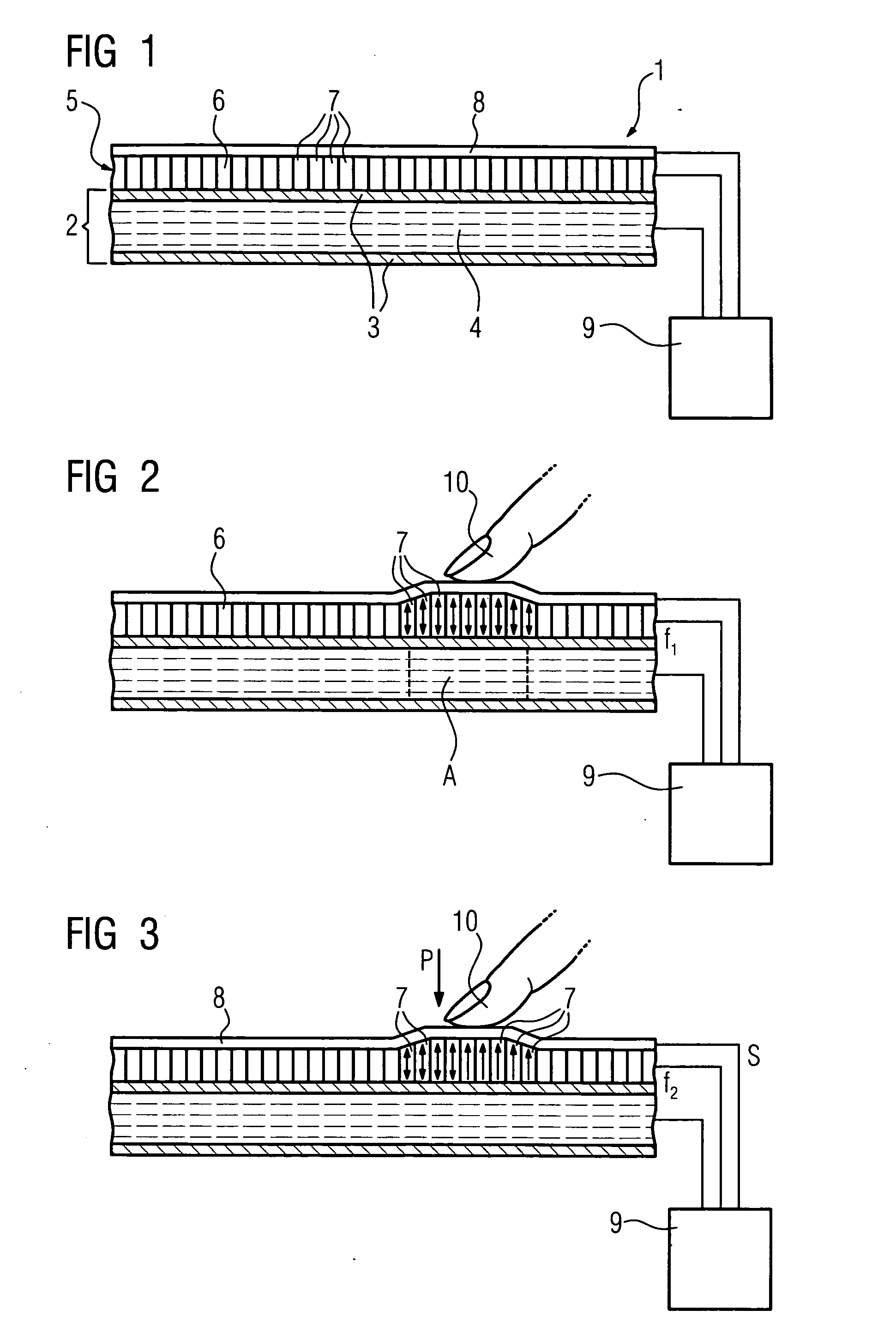
[0022]FIG. 1 shows a touch-sensitive screen 1 according to the invention in the form of a sketch illustrating the principle involved, the essential elements only being shown here. The screen in the embodiment shown comprises an LCD or liquid crystal display plane 2, consisting of a plurality of individual liquid crystal cells that are not shown in further detail, consisting of two upper and lower covering layers 3, the distance between which is generally lower than 10 μm. Each covering layer consists firstly of a glass plate, on the inner side of which transparent electrodes having a special orientation layer are applied. A polyimide layer is generally used as an orientation layer. An ITO (indium-doped tin oxide) layer is preferably used as a transparent electrode material. Between the covering layers 3 is the liquid crystal layer 4. The information content that can be displayed in a liquid crystal display is determined by the structuring of the transparent electrodes, which are man...


PUM


Abstract

Screen having a touch-sensitive user interface (8) for command input via local touching of the user interface (8) and generation of a command signal where the extent of touch is sufficient, comprising electrically actuatable means (5) assigned to the user interface (8) to generate a signal that is haptically perceptible to the user in the position touched on the user interface (8), depending on a command signal being generated.

Description

CROSS REFERENCE TO RELATED APPLICATIONS [0001] This application claims priority to the German application No. 10340188.1, filed Sep. 1, 2003 and which is incorporated by reference herein in its entirety. FIELD OF INVENTION [0002] The invention relates to a screen having a touch-sensitive user interface for command input through localized touching of the user interface and generation of a command signal when the touch is sufficient. BACKGROUND OF INVENTION [0003] Such screens, which are also often referred to as “touch screens,” are sufficiently well known and are used wherever the user communicates interactively with the data processing device assigned to the screen, irrespective of type. In order to make an input that leads to a reaction on the part of the assigned data processing device, irrespective of type, or to the provision of information, and which is generally referred to below as a “command input”, the user simply touches the user interface in the corresponding, optionally...

Claims


Application Information

Patent Timeline
IPC IPC(8): G06F3/041G06F3/00G06F3/01G06F3/03G09G5/00
CPCG06F3/016G09B21/003H01H2003/008G06F2203/04809G06F1/1643G06F3/03547
Inventor KLEEN, MARTIN
Owner SIEMENS AG
Learn More