Bone conduction hearing device with open-ear microphone

a hearing device and microphone technology, applied in the direction of transducer casings/cabinets/supports, electrical transducers, transducer casings/cabinets/supports, etc., can solve the problems of ear infection, noise signal contamination, attenuation of signals, etc., to achieve optimal sound localization (and directionality), natural sound input, and high quality sound input

Active Publication Date: 2013-04-30
SHENGTUO MEDICAL TECH (SHANGHAI) CO LTD
View PDF202 Cites 35 Cited by
  • Summary
  • Abstract
  • Description
  • Claims
  • Application Information

AI Technical Summary

Benefits of technology

[0011]In yet another aspect, a bone conduction hearing aid device includes dual externally located microphones that are placed at the entrance to or in the ear canals and an oral appliance containing dual transducers in communication with each other. The device allows the user to enjoy the most natural sound input due to the location of the microphone which takes advantage of the pinna for optimal sound localization (and directionality) when that(those) sound(s) are transmitted to the cochlea using a straight, signal and “phase-shifted” signal to apply directionality to the patient.
[0013]Implementations of the above aspects may include one or more of the Following. Circuitry coupled to the microphone such as a signal processor, a power supply, a transmitter and an antenna can be positioned in a housing. The circuitry can be located in the Housing either behind an ear or within one or more folds of a pinna. A second microphone can be positioned in or at an entrance of a second ear canal. The microphones receive sound signals from first and second ears and are wirelessly coupled with and vibrate the first and second transducers, respectively. Since sound is directional in nature, the sound level sensed by the microphone at the first ear may be higher in sound level, and arrive first in time at the first microphone. Natural head shadowing and the time of flight of sound spanning the distance between the first microphone at the first ear and the second microphone at the second ear may cause the sound signal received at the second microphone at the second ear to be lower in volume and delayed by a few milliseconds compared to the sound sensed by the first microphone. In the case of a dual transducer oral appliance, the first transducer receives a high sound level from the circuitry associated with the first microphone, and the second transducer receives a lower and slightly delayed sound level from the circuitry associated with the second microphone; this will result in generating an amplitude difference and phase-shifted signal at the second transducer. The first transducer receives a high sound level and the second transducer receives a low sound which is phase-shifted, wherein the high and phase-shifted low sounds add in a cochlea to provide the user with a perception of directionality. The device can include a circuit coupled to the first microphone to filter the audio signal into at least a first frequency range and a second frequency range; wherein the first transducer transmits the first frequency range through the bone of a user; a second microphone positioned at an entrance or in a second ear canal; a circuit coupled to a second microphone to adjust the audio signal with the second frequency range; and a second transducer to transmit the second frequency range through the bone of the user. The second circuit coupled to a second microphone may include an additional phase-shifting circuit to increase or decrease either the audio signal level difference and / or the magnitude of the time delay (phase-shift) of the second audio signal with respect to the first audio signal to enhance the perception of directionality to a greater extent than that provided by the natural attenuation and time delay caused by head shadowing and physical separation of the microphones.
[0018]In one example, an electronics and / or transducer assembly may define a channel or groove along a surface for engaging a corresponding dental anchor or bracket which may comprise a light-curable acrylate-based composite material adhered directly to the tooth surface or a metallic bracket (e.g., stainless steel, Nickel-Titanium, Nickel, ceramics, composites, etc.) attached either directly to the tooth or integrated as part of an oral appliance. The dental anchor may be configured in a shape which corresponds to a shape of channel or groove such that the two may be interfitted in a mating engagement. In this manner, the transducer may vibrate directly against the dental anchor which may then transmit these signals directly into the tooth. Sealing the electronics and / or transducer assembly may facilitate the manufacturing of such devices by utilizing a single size for the electronics encasement which may mount onto a custom-fit retainer or bracket.
[0019]In yet another variation, a bracket may be ferromagnetic or electromagnetic and removably coupled via magnetic attraction to the housing which may also contain a complementary magnetic component for coupling to the magnetic component. The magnetic portion of the bracket may be confined or the entire bracket may be magnetic. One or more alignment members or arms defined along the bracket may facilitate the alignment of the bracket with the housing by aligning with an alignment step.
[0023]Advantages of the system may include one or more of the following. The system allows the user to enjoy the most natural sound input due to the location of the microphone which takes advantage of the pinna for optimal sound localization (and directionality) when the sounds are transmitted to the cochlea using a straight signal and “phase-shifted” signal to apply directionality to the patient. An additional advantage is conveyed by the physical separation of the location of each of the microphones when a first microphone at the first ear and a second microphone at a second ear sense sound level and phase differences with respect to the directional source of the sound, and the difference in these signals is conditioned and transmitted to dual bone conduction transducers which deliver these differences in sound through bone conduction to the two cochlea of the appliance wearer. High quality sound input is captured by placing the microphones within or at the entrance of the ear canal which would allow the patient to use the sound reflectivity of the pinna as well as improved sound directionality due to the microphone placement. The arrangement avoids the need to separate the microphone and speaker as required in air conduction hearing aids to reduce the chance of feedback and allows placement of the microphone to take advantage of the sound reflectivity of the pinna. The system also allows for better sound directionality due to the two bone conduction transducers being in electrical contact with each other. With the processing of the signals prior to being sent to the transducers and the transducers able to communicate with each other, the system provides the best sound localization possible by ensuring that the sound level and phase shift in sound sensed by the two separate microphones are preserved in the delivery of sound via the bone conduction transducers contained within the oral appliance. The system also provides a compact, comfortable, economical, and practical way of exploiting the tooth bone-vibration to configure a wireless intra-oral microphone.
[0024]Another aspect of the invention that is advantageous to the wearer is the housing for the microphone that will locate and temporarily fixate the microphone within the ear canal. The housing will contain at least one, and possibly multiple, opening(s) to enable sound passage from the outside through the housing to the tympanic membrane. This opening will allow passage of at least low frequency sounds, and possibly high frequency sounds, so that the wearer can perceive adequately loud sounds that are within their unassisted auditory range. This will enable the wearer to perceive adequately loud sounds that may not be amplified by the complete system. In addition, when a wearer of this device speaks, bone conduction carries sound from the mouth, to the inner and middle ears, vibrating the tympanic membrane. If the ear canal were completely occluded by the housing containing the microphone the wearer would perceive the sound of their voice as louder than normal, an effect known as occlusion. The opening(s) in the housing will allow the sound radiating from the tympanic membrane to pass through the housing unimpeded, reducing the occlusion effect. Because the amplified transducer of this hearing system is located in an oral appliance, and not in the ear canal as is typical of certain classes of acoustic hearing aids, the openings in this housing will not interfere with the delivery of amplified sounds, and feedback between a speaker located in the same ear canal as a microphone in an acoustic hearing aid will be commensurately reduced.

Problems solved by technology

Although the above-referred devices have been successfully marketed, there are many drawbacks.
First, since the skin is present between the sensor and the bones .the signal is attenuated and may be contaminated by noise signals.
This pressure results in discomfort for the wearer of the microphone.
Furthermore, they can lead to ear infection (in case of ear microphone) and headache (in case of scalp and jaw bone microphones) for some users.

Method used


Image

  • Bone conduction hearing device with open-ear microphone
  • Bone conduction hearing device with open-ear microphone
  • Bone conduction hearing device with open-ear microphone

Examples


Embodiment Construction

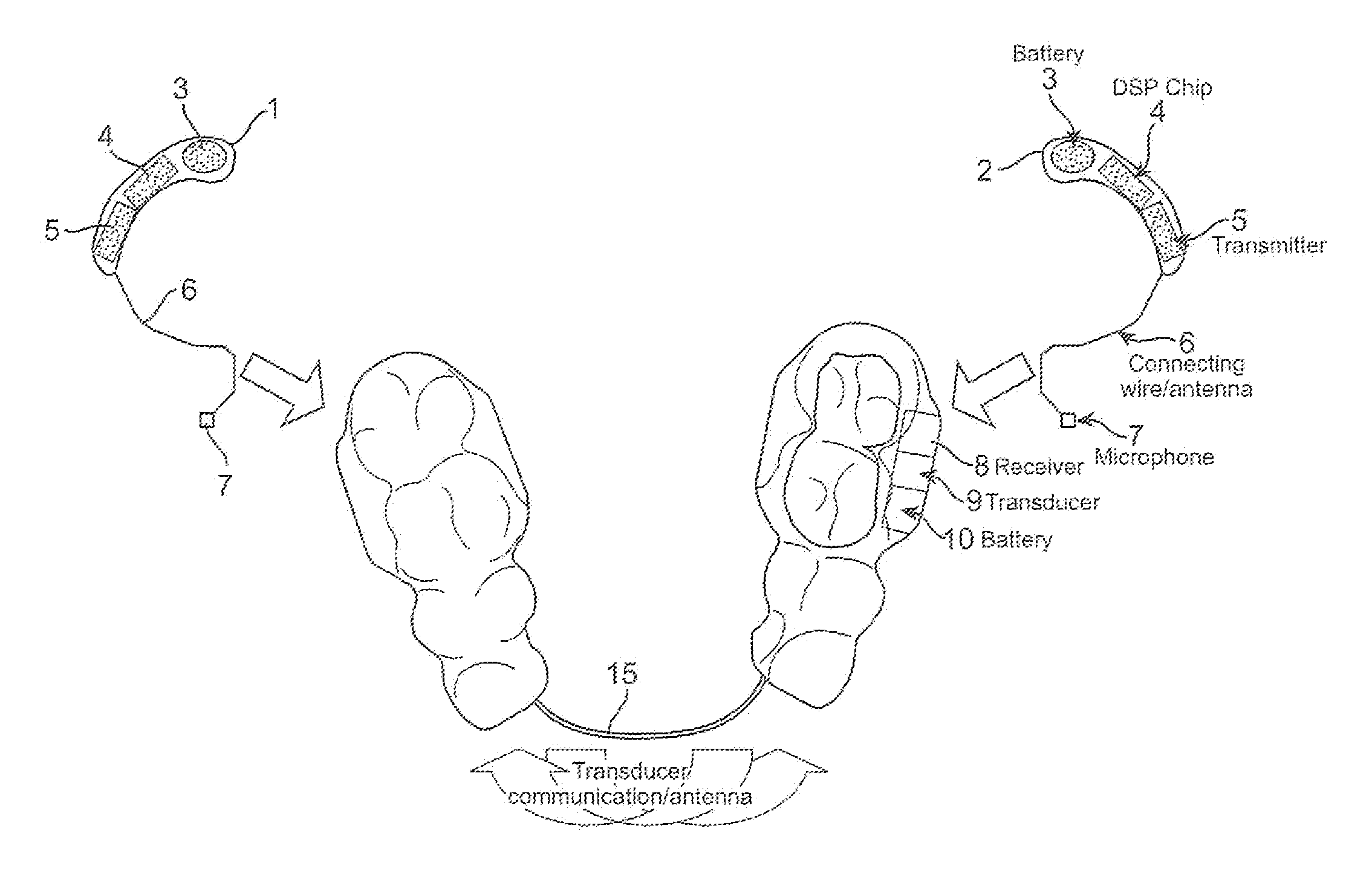
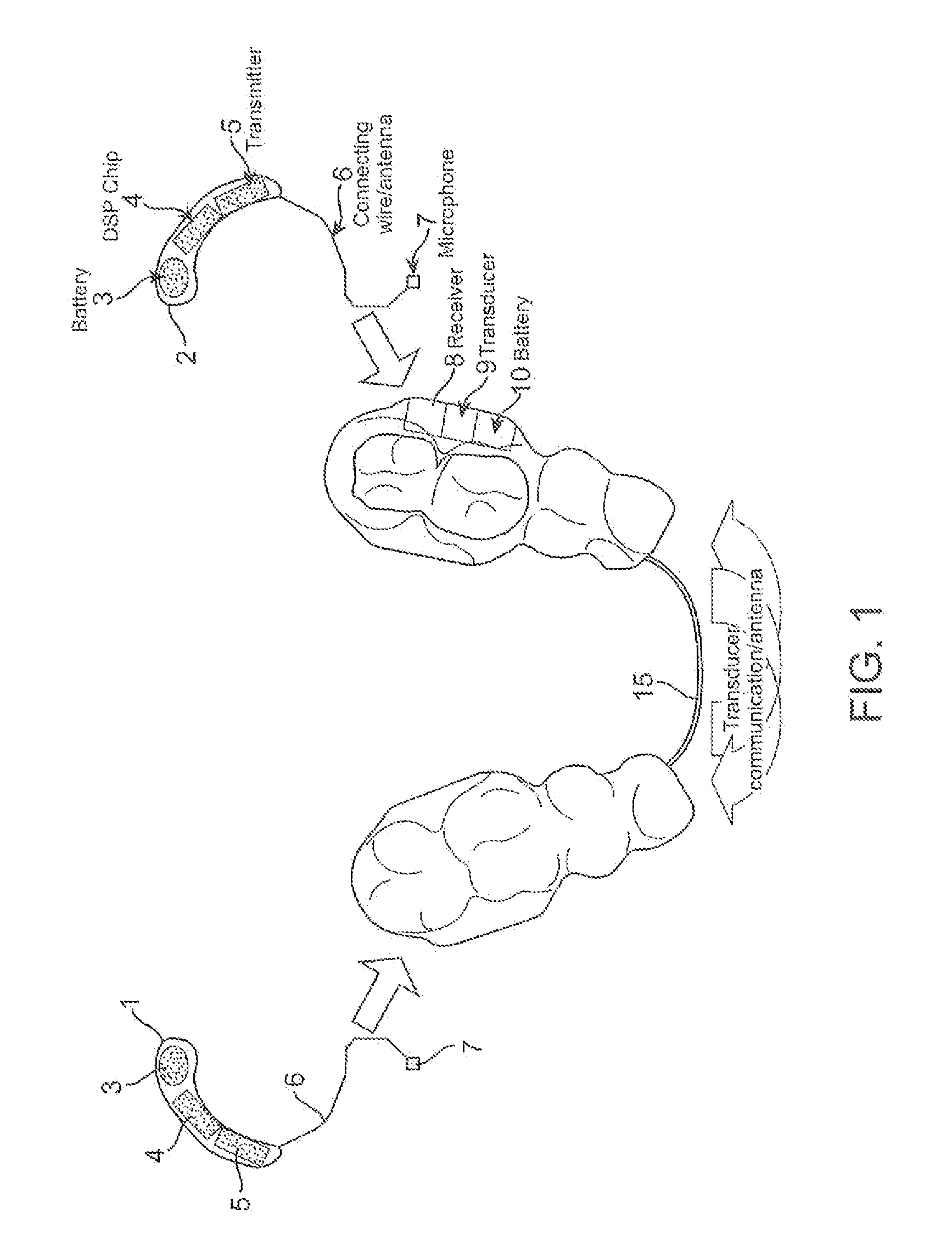
[0032]FIG. 1 shows an exemplary ear canal mounted hearing sub-systems 1 and 2. The system of FIG. 1 processes sound signals from each of two microphones 7. The microphones 7 are placed either at the opening or directly with the user's ear canals. Each of the systems 1-2 includes a battery 3, a signal processor 4, a transmitter 5, all of which can be positioned in a housing that clips onto the ear which rests behind the ear between the pinna and the skull, or alternatively can be positioned in the ear's concha. The transmitter 5 is connected to a wire / antenna 6 that in turn is connected to the microphone 7.

[0033]Each transmitter 5 transmits information to a receiver 8 that activates a transducer 9 that is powered by a battery 10. Each side of the head can have one set of receiver 8, transducer 9 and battery 10. This embodiment provides a bone conduction hearing aid device with dual externally located microphones that are placed at the entrance to or in the ear canals and an oral appl...


PUM


Abstract

Systems and methods for transmitting an audio signal through a bone of a user includes receiving an audio signal from a first microphone positioned at an entrance or in a first ear canal; and vibrating a first transducer to audibly transmit the audio signal through the bone. A second microphone can be positioned in a second ear canal and the two microphones preserve and deliver inter-aural sound level and phase differences that naturally occur so that the user can perceive directionality.

Description

BACKGROUND OF THE INVENTION[0001]The present invention relates to methods and apparatus for transmitting vibrations through teeth or bone structures in and / or around a mouth.[0002]The human ear can be generally classified into three regions; the outer ear, the[0003]middle ear, and the inner ear. The outer ear generally comprises the external auricle and the ear canal, which is a tubular pathway through which sound reaches the middle ear. The outer ear is separated from the middle ear by the tympanic membrane (eardrum). The middle ear generally comprises three small bones, known as the ossicles, which form a mechanical conductor from the tympanic membrane to the inner ear. Finally, the inner ear includes the cochlea, which is a fluid-filled structure that contains a large number of delicate sensory hair cells that are connected to the auditory nerve.[0004]The action of speaking uses lungs, vocal chords, reverberation in the bones of the skull, and facial muscle to generate the acoust...

Claims


Application Information

Patent Timeline
Patent Type & Authority Patents(United States)
IPC IPC(8): H04R25/00
CPCH04R25/606H04R2460/13
Inventor RADER, RICHARD SCOTTABOLFATHI, AMIR
Owner SHENGTUO MEDICAL TECH (SHANGHAI) CO LTD
Why Eureka
Try Eureka