Print head driving circuit

a driving circuit and printing head technology, applied in printing, other printing apparatus, etc., can solve the problems of reducing printing quality, reducing printing quality, and reducing the risk of color fluctuation in printing using magenta ink, so as to prevent the decline in printing quality

Inactive Publication Date: 2005-03-17
SEIKO EPSON CORP
View PDF1 Cites 9 Cited by
  • Summary
  • Abstract
  • Description
  • Claims
  • Application Information

AI Technical Summary

Benefits of technology

[0008] Therefore, it is an object of the present invention to provide a print head driving circuit whereby, even if the load changes, the accuracy of the driving voltage waveform supplied to the load can be maintained, and consequently, decline in printing quality can be prevented.

Problems solved by technology

Therefore, cases may occur where the base voltage of the transistor 54a rises in excess of the prescribed value, giving rise to distortion in the nozzle drive voltage waveform output by the current amplifying circuit 54.
In an inkjet printer provided with a print head driving circuit as illustrated in FIG. 1, if waveform distortion such as that described above occurs in the nozzle drive voltage, in other words, if the accuracy of the nozzle drive voltage waveform falls, then this risks causing a decline in printing quality.
For example, if, in the middle of simultaneously performing printing using cyan ink and printing using magenta ink, for example, the printer changes suddenly from a state of solid printing of cyan ink to a state where no cyan ink is to be printed, then there is a risk that color fluctuation will occur in the printing using magenta ink.

Method used


Image

  • Print head driving circuit
  • Print head driving circuit
  • Print head driving circuit

Examples


Embodiment Construction

[0029] Below, an embodiment of the present invention is described in detail with reference to the drawings.

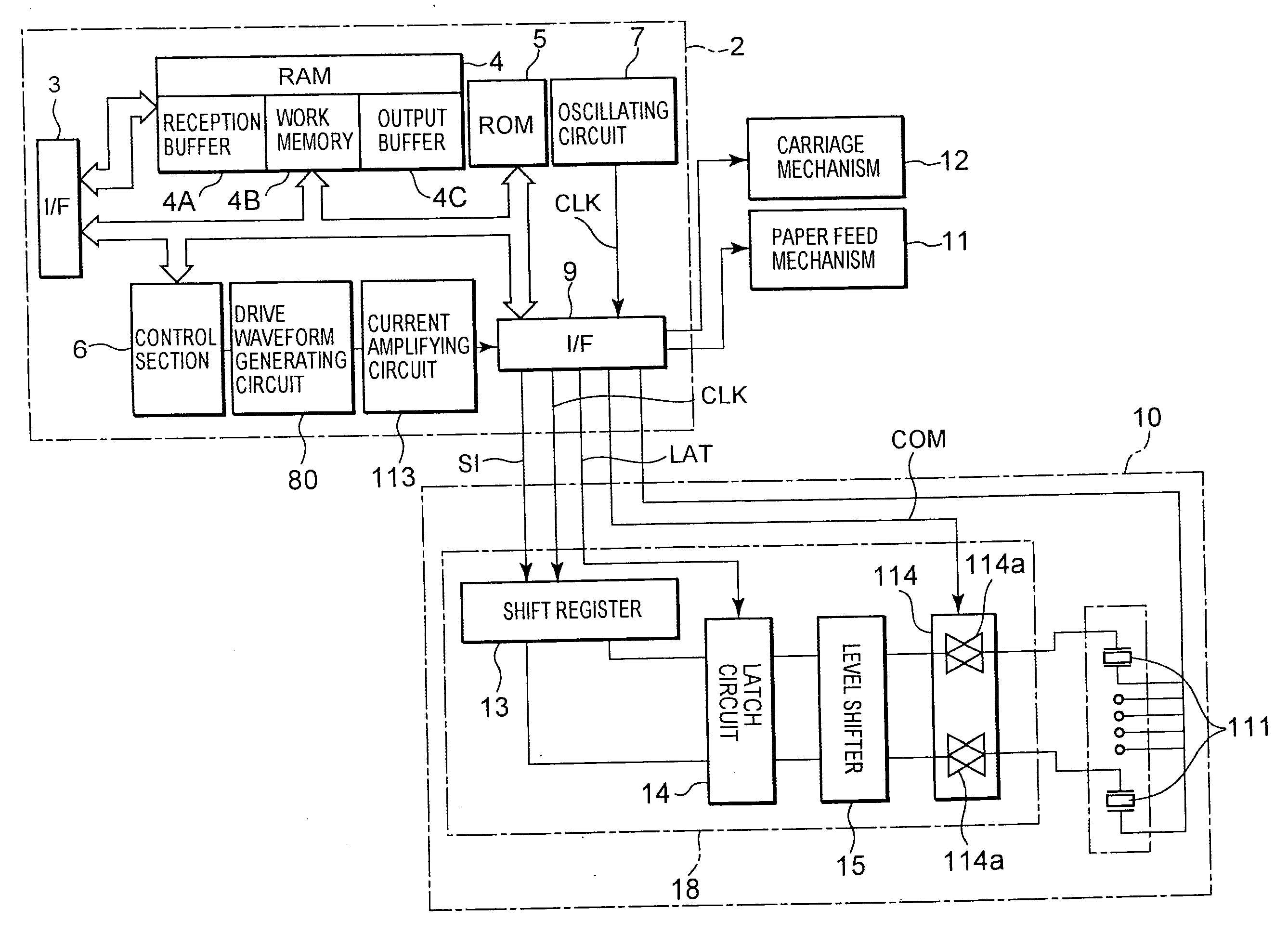
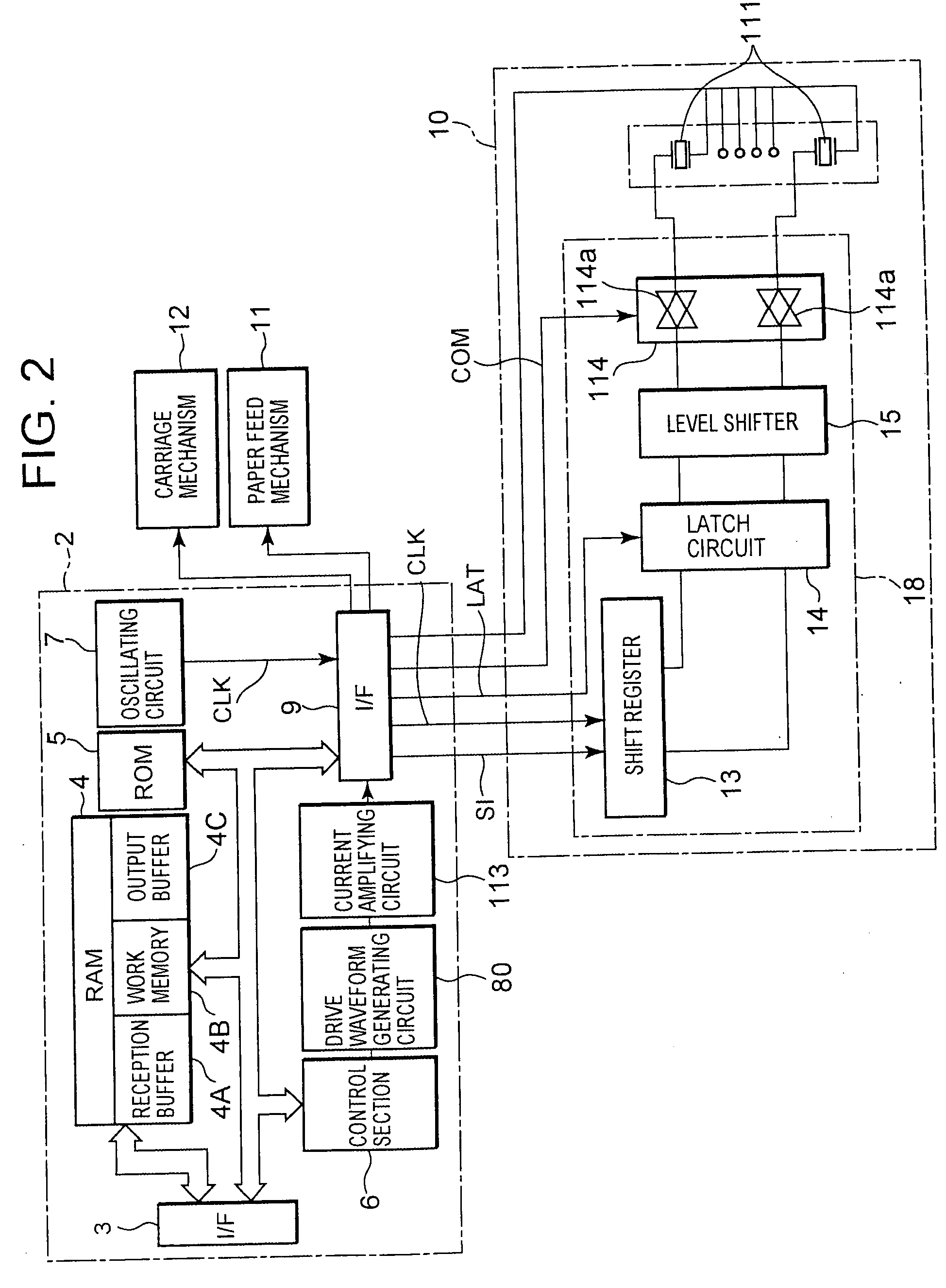
[0030]FIG. 2 is a functional block diagram showing the overall composition of an inkjet printer (hereinafter, called “printer”) provided with a print head driving circuit relating to one embodiment of the present invention.

[0031] As shown in FIG. 2, the printer comprises a printer main body 2, a print head 10, a paper feed mechanism 11 and a carriage mechanism 12. The printer main body 2 comprises an interface (hereinafter, called “I / F”) 3, a RAM 4, a ROM 5, a control section 6, an oscillating circuit 7, an interface (hereinafter called “I / F 9”, similarly to the “I / F 3”), a drive waveform generating circuit 80, and a current amplifying circuit 113.

[0032] The print head 10 is connected to the printer main body 2 by means of a signal transmission cable, such as a flexible flat cable (FFC), for example, and it comprises a plurality of nozzle openings (for example, 96 nozzle ope...


PUM


Abstract

A print head driving circuit is provided whereby, even if the load changes, the accuracy of the driving voltage waveform supplied to the load can be maintained, and consequently, deterioration in printing quality can be prevented. Transistors Q3, Q4 connected in a push-pull configuration are connected to the upstream of a transistor Q1. If the base potential of the transistor Q1 rises above its normal level, then the emitter potential of the transistors Q3, Q4 will rise and the transistor Q3 will become non-conductive, and the transistor Q1 will also become non-conductive, but since the transistor Q4 is conductive, the current I2 will flow from the base terminal of the transistor Q1, to earth, via the transistor Q4, and hence the base potential of the transistor Q1 will fall to or below the prescribed value. As a result, it is possible to prevent the base potential of the transistor Q1 from rising up in excess of the prescribed value.

Description

CROSS-REFERENCE TO PRIOR APPLICATION [0001] This application relates to and claims priority from Japanese Patent Application No. 2003-103356 filed on Apr. 7, 2003, the entire disclosure of which is incorporated herein by reference. BACKGROUND OF THE INVENTION [0002] 1. Field of the Invention [0003] The present invention relates to a print head driving circuit for driving a print head having a plurality of nozzles. [0004] 2. Description of the Related Art [0005] Conventionally, in an inkjet printer, a print head drive voltage waveform generating circuit and drive voltage waveform generating method have been proposed, with the object of obtaining a desired waveform, in a programmable fashion, by means of a simple operation. In these proposals, data for a plurality of points in a plurality of drive voltage waveforms at a prescribed temperature are previously stored as absolute coordinate data, and the data for a plurality of points in a desired drive voltage waveform are read out on th...

Claims


Application Information

Patent Timeline
Patent Type & Authority Applications(United States)
IPC IPC(8): B41J2/045B41J2/05B41J2/055
CPCB41J2/04541B41J2/04588B41J2/04581B41J2/0457
Inventor UMEDA, ATSUSHI
Owner SEIKO EPSON CORP
Why Eureka
Try Eureka