
Liquid container

a liquid container and container technology, applied in printing and other directions, can solve the problems of leakage of ink, increased carriage weight, and large load on the carriage motor

Inactive Publication Date: 2005-03-17
SEIKO EPSON CORP
View PDF24 Cites 38 Cited by
  • Summary
  • Abstract
  • Description
  • Claims
  • Application Information

AI Technical Summary

Benefits of technology

The invention is a liquid container with a space portion that prevents liquid from flowing through the fitting portions, even if liquid flows out of the container. This prevents liquid smear and ensures that liquid does not flow to the cartridge inserting portion, which could be smeared. The space portion is formed between the front surface of the container case and the support portion, and a reception opening is formed in the support portion to receive a liquid introducing member. The fitting portions are arranged so as to traverse the reception opening, and the space portion is located near the front surface of the container case. The invention also includes a circuit board that mounts storing means that stores liquid information.

Problems solved by technology

In such a case, since an amount of ink consumption increases, there is a demand for an ink cartridge that can store a large quantity of ink.
If such a large capacity ink cartridge is mounted on a carriage, weight of the carriage increases, and it is likely that a great deal of load is applied to a carriage motor or the like.
When the ink cartridge is detached, leakage of ink occurs because surfaces of exposed ink supply needles are wet with ink or a slight amount of ink scatters in a transition period of the detachment of the ink cartridge.
However, the ink cartridge has a problem in that, since the circuit board is close to a position to which ink is supplied and a position from which the ink is discharged, the ink adheres to the circuit board due to scattering, dripping, or the like of the ink.

Method used


Image

  • Liquid container
  • Liquid container
  • Liquid container

Examples


first embodiment

[0069] First Embodiment

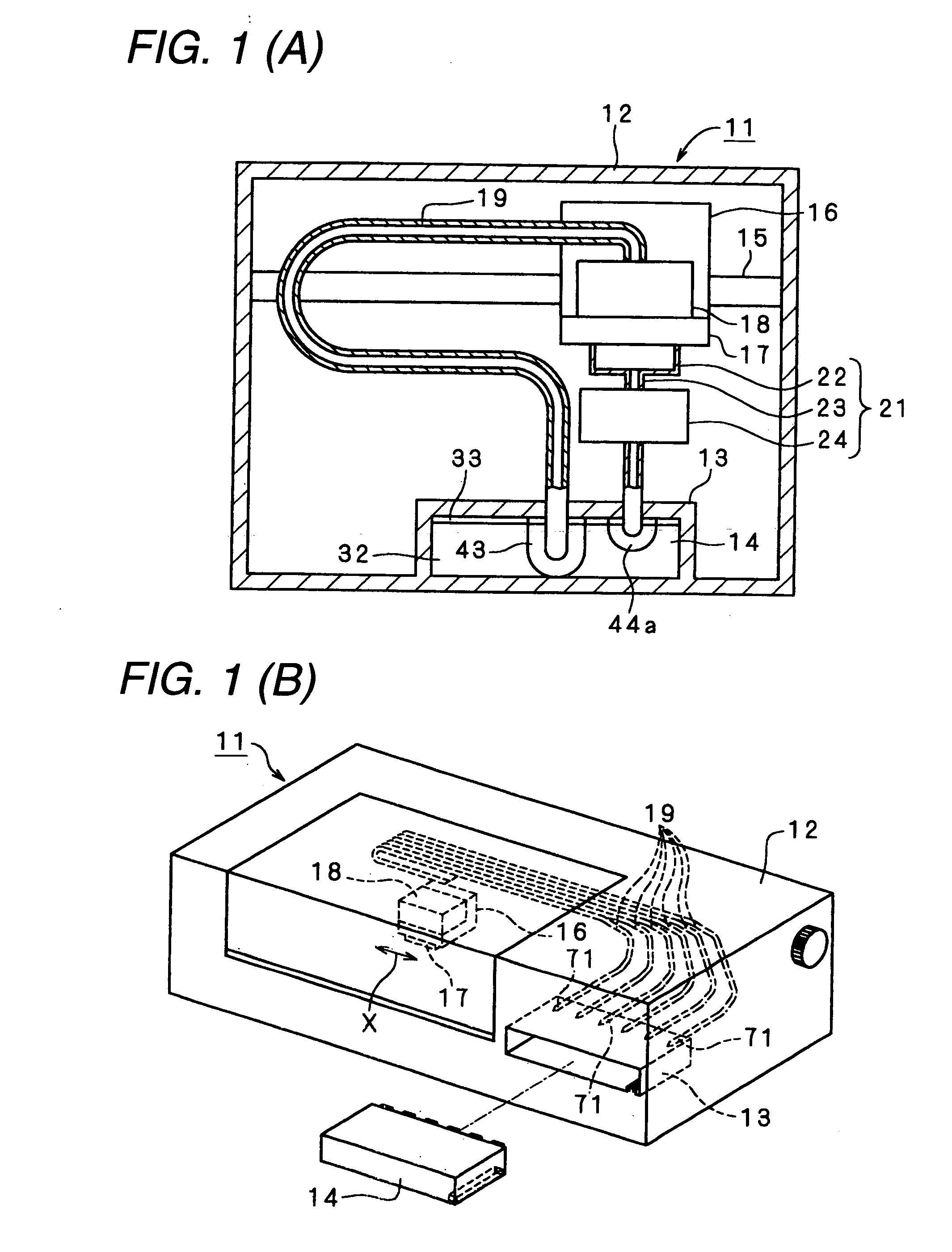
[0070]FIG. 1A is a conceptual diagram of an ink-jet type printer (hereinafter referred to as printer) serving as a liquid ejection apparatus, and FIG. 1B is a simple perspective view showing an overall shape of the printer. Note that the printer of the embodiment is a printer of an off-carriage type that is not mounted with an ink cartridge serving as a liquid container on a carriage, which is a small and thin printer with a degree of freedom given to a layout of the ink cartridge.

[0071] As shown in FIG. 1, a printer 11 includes a frame 12, and a cartridge inserting portion 13 is formed in a lower part of the frame 12. An ink cartridge 14 serving as a liquid container is detachably inserted in this cartridge inserting portion 13. Note that this ink cartridge 14 is capable of storing ink as liquid and storing waste ink as waste liquid. Details of the ink cartridge 14 will be described later.

[0072] The printer 11 includes a guide member 15, and the guide membe...


PUM


Abstract

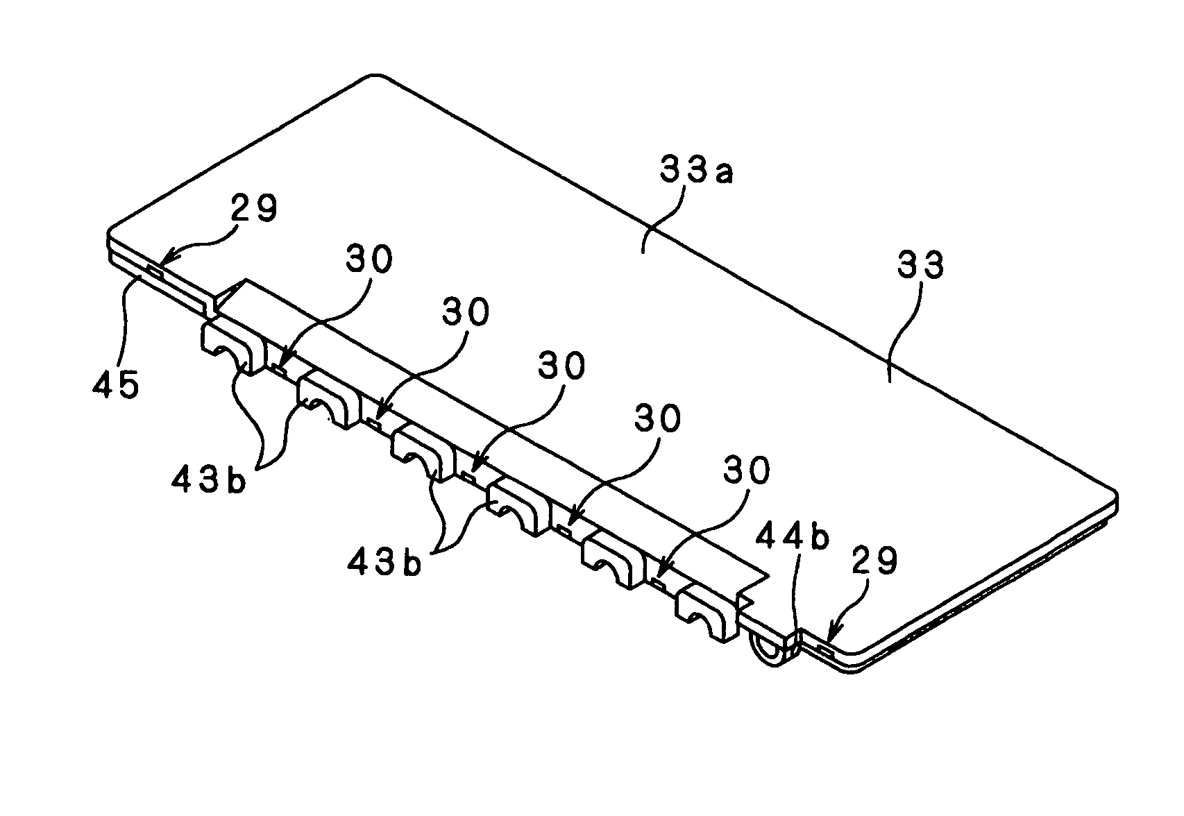
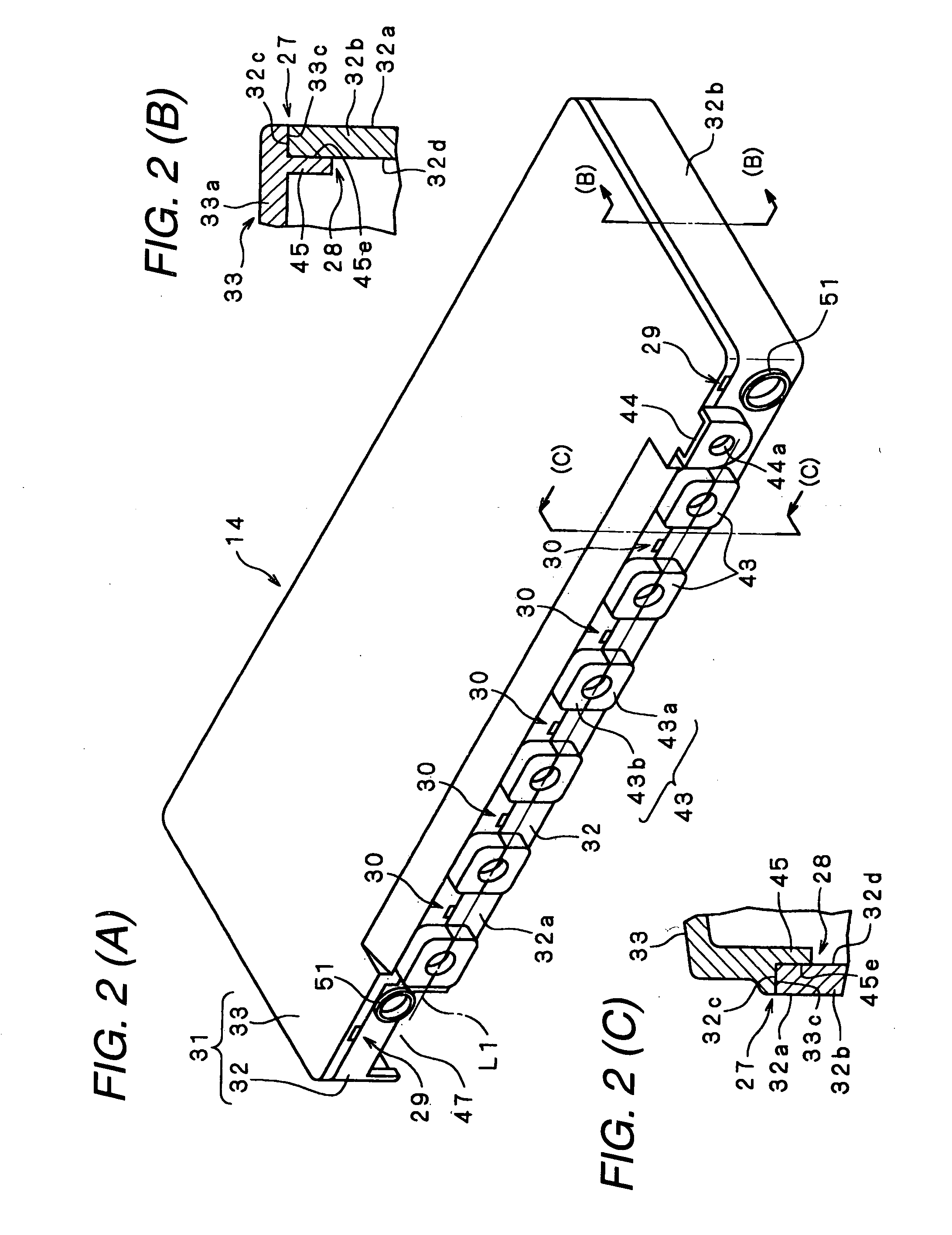
Liquid packs 34 provided with liquid leading members 42 are stored in a container case 31 that is constituted by fitting a case main body portion 32 and a lid case 33 in fitting portions 27 and 28, support portions 13, which positions the liquid leading members 42 so as to be opposed to liquid introducing members 71 attached to a cartridge inserting portion 13, are provided on a front surface 32a of the container case 31, the fitting portions 27 and 28 are arranged in a state in which the fitting portions 27 and 28 traverses the support portions 43, and space portions 29 and 30 having a gap larger than a gap formed in the fitting portions 27 and 28 are formed near the support portions 43 in the fitting portions 27 and 28. In this way, liquid flowing through the fitting portions 27 and 28 due to the capillarity is retained by the space portions 29 and 30 and never flows to the fitting portions 27 and 28 further extending from the space portions 29 and 30.

Description

BACKGROUND OF THE INVENTION [0001] 1. Field of the Invention [0002] The present invention relates to a liquid container. [0003] 2. Description of the Related Art [0004] As one of liquid ejection apparatuses that eject liquid on a target, an ink-jet type printer is widely used. This ink-jet type printer includes a carriage and a recording head mounted on the carriage. The ink-jet type printer discharges ink from nozzles formed in the recording head to perform printing on a recording medium while moving the carriage with respect to the recording medium. In addition, in such an ink-jet type printer, an ink cartridge serving as a liquid container for storing ink is provided replaceably, and the ink discharged from the recording head is supplied from the ink cartridge. [0005] Incidentally, in recent years, in the ink-jet type printer described above, printing has been performed on a large print sheet such as an AO size sheet. In such a case, since an amount of ink consumption increases, ...

Claims


Application Information

Patent Timeline
Patent Type & Authority Applications(United States)
IPC IPC(8): B41J2/165B41J2/175
CPCB41J2/16523B41J2/175B41J2/17509B41J2002/17516B41J2/17553B41J2002/1728B41J2/17513B41J2/1728
Inventor KIMURA, HITOTOSHISAKAI, YASUTOSHINADA, SATOSHITSUKAHARA, MICHINARIKOBAYASHI, MASANORIISHIZAWA, TAKU
Owner SEIKO EPSON CORP
Learn More