Tachograph with cubic housing and printing device

a printing device and tachograph technology, applied in the field of tachographs with cubic housings and printing devices, can solve the problems of making the sealing of the front panel with respect to the front wall of the tachograph considerably more difficult in the locked state of the carrier, and the esthetically unfavorable gripping of the front panel of the carrier, so as to achieve the effect of convenient fitting

Inactive Publication Date: 2005-03-17
CONTINENTAL AUTOMOTIVE GMBH
View PDF10 Cites 12 Cited by
  • Summary
  • Abstract
  • Description
  • Claims
  • Application Information

AI Technical Summary

Benefits of technology

[0007] An object of the present invention is to provide for a printing device of the generic type used in a tachograph having functionally reliable locking means which can be handled in a simple manner in respect of being unlocked and which meet the requirements of mass production by means of simple components which can easily be fitted.
[0013] Further advantageous refinements of the invention emerge from the following description and the attached drawings. Apart from the fact that it achieves the set object in a satisfactory manner, the invention provides the advantage of being able to be used both in a structural concept, in which the entire printing device is assigned to the carrier, in which case suitable measures for forming the stops and snap-in members have to be taken in the housing of the tachograph in question, and also in the preferred exemplary embodiment which envisages the thermal print head and feed roller being separated in the event of a ribbon being reloaded. Furthermore, in the case of the preferred exemplary embodiment, the latch elements are used for exactly aligning the feed roller with the thermal element strip.
[0014] The invention provides a particular effect by virtue of the fact that, when the carrier is locked by means of the pushbutton mounted in the front panel, the latch elements are pivoted and then, by the actuating arms being supported on the stops, a deflection of force causes the carrier to be displaced in the direction of the insertion position, so that, on the one hand, when the pushbutton is released, re-locking is prevented and, on the other hand, the frictional connection between the thermal print head and the feed roller is released, if appropriate with a pressure point caused by snap-in lugs being overcome. In this case, the actuation of the pushbutton by hand and the pivoting of the latch elements over a sloping plane permit a relatively strong tension spring which acts on the latch elements, and therefore enable a sufficiently high security against shocks.
[0015] It is furthermore advantageous that, after the carrier is unlocked and after the pushbutton is released, the push-in device assigned to the carrier is used to displace the carrier into a gripping position. In this case, the compression spring assigned to the push-in device is dimensioned in such a manner that it overcomes at least the friction of the carrier in its guide and therefore only an insignificant amount of force is required in addition to the effort necessary during the closing of the carrier to pivot the latch elements and raise the thermal print head when bringing the feed carrier into the printing position. The closed position of the carrier is signaled by means of switches assigned directly to the latch elements.

Problems solved by technology

These devices have to be arranged inside the tachographs since there is generally not enough space in a driver's cab of a commercial vehicle for the installation of an independent printer which corresponds with the tachograph.
One problem is, however, that tachographs are generally designed as built-in appliances and are therefore fitted with a flush front wall so that access for reloading the stock of printing material is only possible from the front side using a carrier which can be displaced in the manner of a drawer or can be pivoted open / folded open on the front side.
Apart from the outlay and an unreliable performance in respect of security against shocks because of the not inconsiderable mass of the carrier, the bistable snap-in mechanism requires the carrier to be able to be moved in the locked state, in the direction of the rear wall of the housing of the tachograph, which makes sealing of the front panel with respect to the front wall of the tachograph considerably more difficult in the locked state of the carrier.
In such a printing device, the relatively high press-on force of the thermal print head obstructs the ability of the carrier to move, and so the snap-in mechanism has to be equipped with an extremely strong ejection spring or the carrier has to be pulled out by hand after being unlocked, which, apart from being disadvantageous to handle, requires esthetically unfavorable gripping means to be provided on the front panel of the carrier.

Method used


Image

  • Tachograph with cubic housing and printing device
  • Tachograph with cubic housing and printing device
  • Tachograph with cubic housing and printing device

Examples


Embodiment Construction

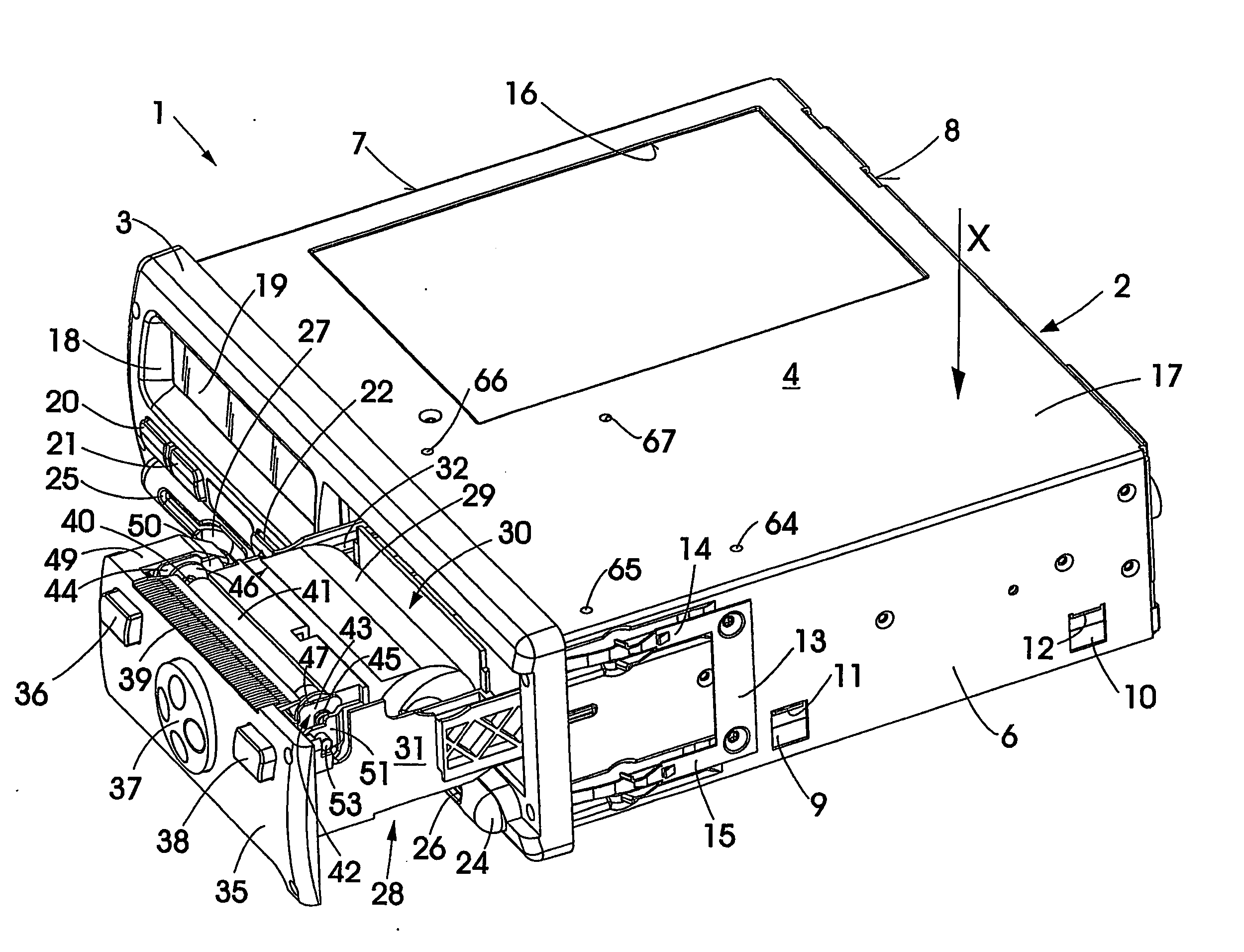
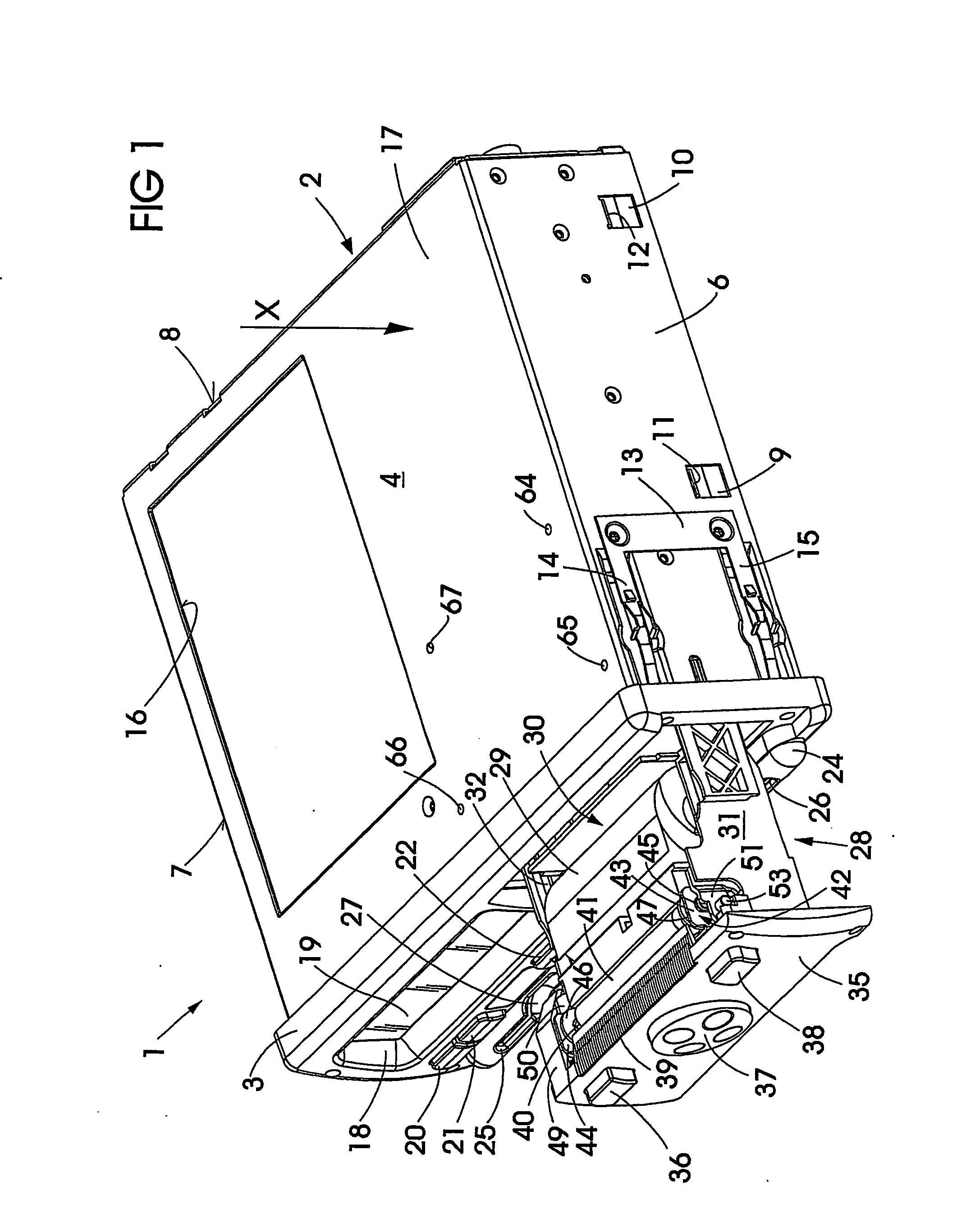
[0021] The tachograph 1 which is illustrated by FIG. 1 has a built-in housing part 2 and a front panel 3 fastened to the latter. The built-in housing part 2 comprises a cover part 4 and a bottom part 5, side walls 6 and 7 and also a rear wall 8 being integrally formed on the cover part 4. Limbs overlapping the side walls 6, 7 and the rear wall 8 are integrally formed on the bottom part 5 and on them latches, two 9 and 10 of which can be seen in FIG. 1, are formed. When the cover part 4 and base part 5 are joined together, said latches can be brought into engagement in a bayonet-like manner with tabs 11 and 12 which are formed on the side walls 6, 7. U-shaped components 13, the limbs of which are designed as resilient claws 14 and 15, are fastened on both side walls 6, 7 for the purpose of fastening the tachograph 1 in a built-in compartment or in a suitable opening, for example in a dashboard. A depression provided in the cover panel 17 for a nameplate is referred to by 16. A window...


PUM


Abstract

A tachograph has a cubic housing and a printing device having a thermal print head, a feed roller driven by a drive mechanism and a carrier movable out of the housing to reload a ribbon which forms a stock of printing material. Locking means lock and unlock the carrier in a closed position in the housing. A latch element is mounted rotatably on the carrier and subjected to an action of a tension spring. A snap-in hook of the latch element is associated with a snap-in member in a fixed position. An actuating arm is formed with the latch element, and a pushbutton is configured to be in operative connection with the actuating arm and mounted displaceably on the carrier. A fixed stop associated with the actuating arm disengages the latch element from the snap-in member when the pushbutton is actuated, and displaces the carrier in a direction of an insertion position when the actuating arm is supported on the stop.

Description

CROSS-REFERENCE TO RELATED APPLICATIONS [0001] The present application is a continuation of international application number PCT / DE03 / 00983, filed on Mar. 25, 2003, which designates the United States of America, and further claims priority of German patent application number DE 10215122.9, filed on Apr. 5, 2002, the both of which are herein incorporated by reference. BACKGROUND OF THE INVENTION [0002] The invention relates to a tachograph having a cubic housing and a printing device, which has a thermal print head, a feed roller which is driven by a drive mechanism, and a carrier which can be moved out of the housing and is used for reloading a ribbon which forms the stock of printing material, and further having means for locking and unlocking the carrier in its closed position in the housing of the tachograph. [0003] Tachographs which are not designed for the use of record charts as recording media, but rather in which the driving and working time data determined are stored in sui...

Claims


Application Information

Patent Timeline
Patent Type & Authority Applications(United States)
IPC IPC(8): G07C5/00G01D9/00G07C7/00
CPCB41J15/042G07C7/00
Inventor HUEGLE, AXEL
Owner CONTINENTAL AUTOMOTIVE GMBH
Why Eureka
Try Eureka