
Method and apparatus for forwarding packets in an ethernet passive optical network

a passive optical network and packet forwarding technology, applied in the field of design, can solve the problems of limited bandwidth offered by current access networks, inability to provide integrated services with dsl or cm technology, and inability to meet the needs of end users,

Active Publication Date: 2005-03-17
AVAGO TECH INT SALES PTE LTD
View PDF7 Cites 125 Cited by
  • Summary
  • Abstract
  • Description
  • Claims
  • Application Information

AI Technical Summary

Benefits of technology

[0031] In a variation of this embodiment, the system maintains knowledge at the central node of all active multicast groups within the EPON. If a remote node sends a message to join that multicast group of which no remote node is a member, the system sends a message from the central node to a multicast source to join a multicast group. The system also receives a multicast packet at the central node on behalf of a number of remote nodes which are members of a multicast group, and broadcasts the multicast packet from the central node to every remote node, thereby eliminating the need for transmitting a separate copy of the multicast packet to each remote node which is a member of the multicast group.

Problems solved by technology

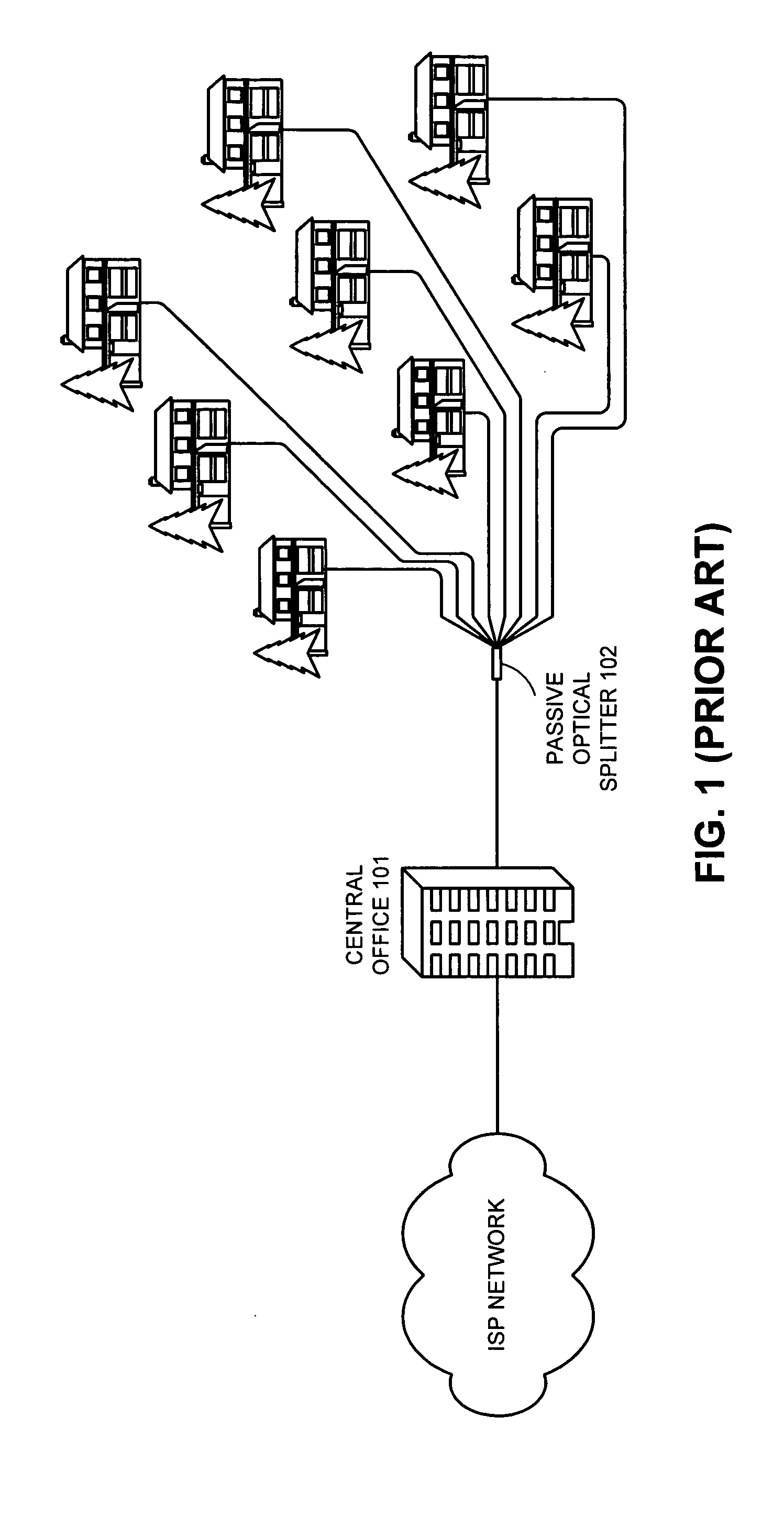
However, this increase in the capacity of backbone networks has not been matched by a corresponding increase in the capacity of access networks.
Even with broadband solutions, such as digital subscriber line (DSL) and cable modem (CM), the limited bandwidth offered by current access networks creates a severe bottleneck in delivering high bandwidth to end users.
Such integrated service is difficult to provide with DSL or CM technology.
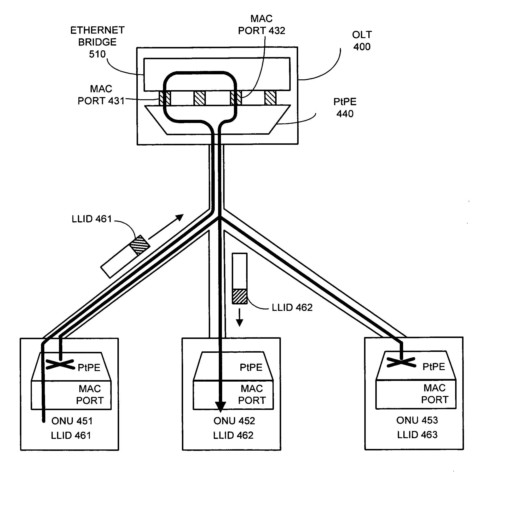
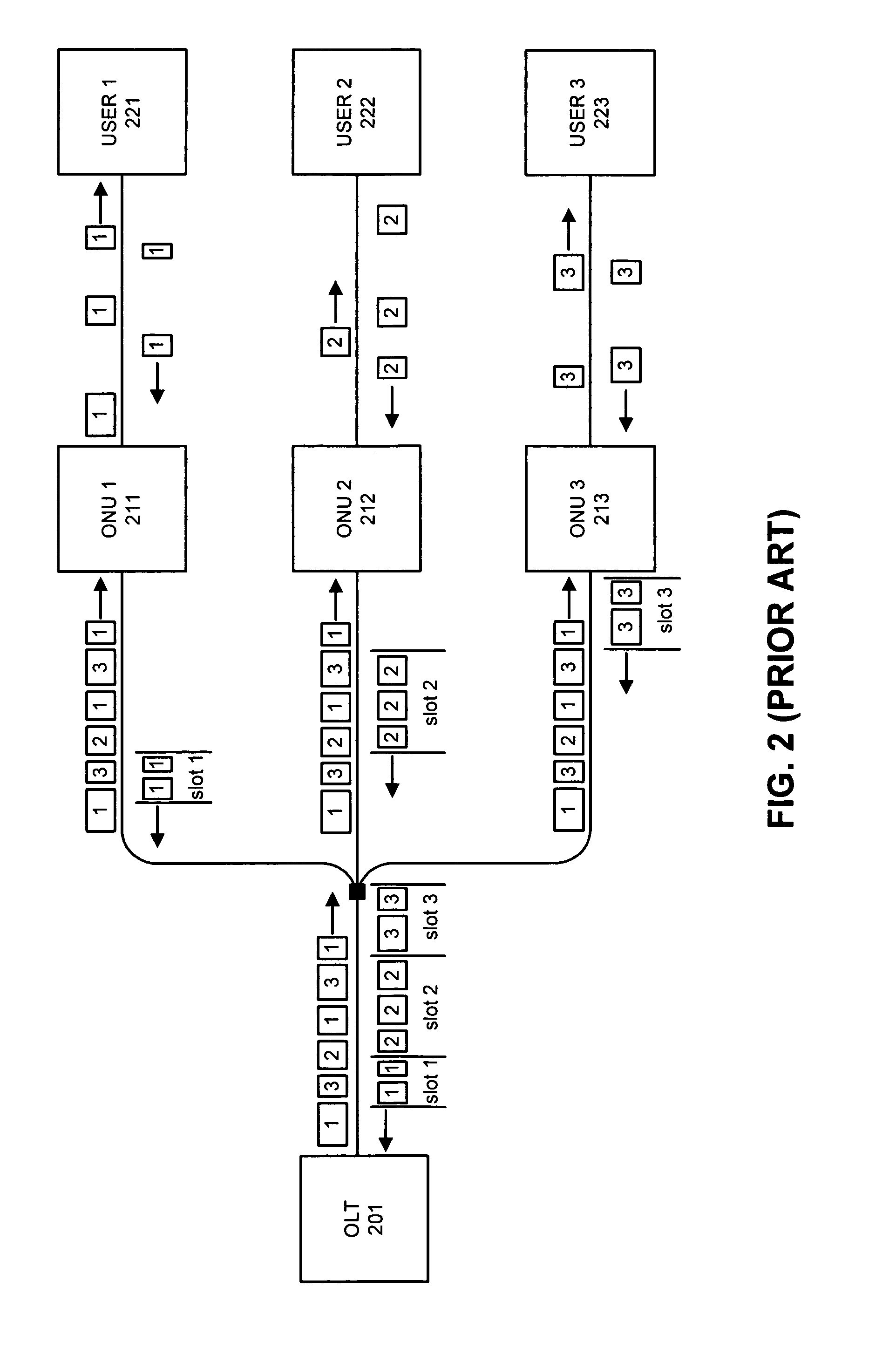
The tree topology of an EPON, however, presents a problem: if the head end (OLT side) of the upstream link is coupled to one single port of the bridge residing in the OLT, the bridge will not forward any frames sent by an ONU to another ONU.
Although PtPE solves the bridging issue, the default bridge behavior of an OLT still has limitations.
For example, the default flooding of a frame with unknown MAC destination address is not desirable.
Such behavior is generally not desired for privacy purposes.
Another limitation is that an OLT does not process information outside the Ethernet header, thereby prohibiting implementation of more intelligent switching functions.

Method used


Image

  • Method and apparatus for forwarding packets in an ethernet passive optical network
  • Method and apparatus for forwarding packets in an ethernet passive optical network
  • Method and apparatus for forwarding packets in an ethernet passive optical network

Examples


Embodiment Construction

[0056] The following description is presented to enable any person skilled in the art to make and use the invention, and is provided in the context of a particular application and its requirements. Various modifications to the disclosed embodiments will be readily apparent to those skilled in the art, and the general principles defined herein may be applied to other embodiments and applications without departing from the spirit and scope of the present invention (e.g., general passive optical network (PON) architectures). Thus, the present invention is not intended to be limited to the embodiments shown, but is to be accorded the widest scope consistent with the principles and features disclosed herein.

[0057] The data structures and procedures described in this detailed description are typically stored on a computer readable storage medium, which may be any device or medium that can store code and / or data for use by a computer system. This includes, but is not limited to, applicati...


PUM


Abstract

One embodiment of the present invention provides a system that facilitates forwarding of packets in an Ethernet passive optical network (EPON), which includes a central node and at least one remote node. During operation, the system assigns a logical link identifier (LLID) to a remote node, wherein an LLID corresponds to a logical link between the central node and a remote node. The system also associates an LLID with a port of a switch within the central node, wherein the switch has a number of ports; wherein a port may be a physical port or a virtual port; and wherein the number of ports on the switch are divided into network-side ports and user-side ports. Upon receiving a downstream packet from a network-side port, the system searches a mapping table to determine whether one or more field values of the downstream packet correspond to any LLIDs or ports. If the one or more field values correspond to an LLID, the system assigns the LLID to the downstream packet and transmits the downstream packet to a remote node.

Description

RELATED APPLICATION [0001] This application hereby claims priority under 35 U.S.C. §119 to the following provisional patent applications: U.S. Provisional Patent Application No. 60 / 502,412 filed on 15 Sep. 2003, entitled “Method for VLAN Translation in Ethernet Point-to-multipoint Network,” by inventors Lawrence Drew Davis, Edward Wayne Boyd, and Glen Kramer; U.S. Provisional Patent Application No. 60 / 566,517 filed on 28 Apr. 2004, entitled “Method for VLAN Mapping to Support Triple-play Services in Ethernet Passive Optical Networks,” by inventor Edward Wayne Boyd; and U.S. Provisional Patent Application No. 60 / 570,928 filed on 13 May 2004, entitled “Method for Service Differentiation in EPON Using ONU-Based Data Classification,” by inventor Edward Wayne Boyd. BACKGROUND [0002] 1. Field of the Invention [0003] The present invention relates to the design of Ethernet passive optical networks. More specifically, the present invention relates to a method and apparatus for forwarding pac...

Claims


Application Information

Patent Timeline
Patent Type & Authority Applications(United States)
IPC IPC(8): H04Q11/00
CPCH04L12/2856H04L12/2861H04L12/4641H04Q11/0071H04L12/467H04Q11/0066H04Q11/0067H04L12/4645H04B10/27H04Q11/00
Inventor DAVIS, LAWRENCE D.BOYD, EDWARD W.KRAMER, GLEN
Owner AVAGO TECH INT SALES PTE LTD
Learn More