Orthopaedic brace having a range of motion hinge with an adjustable-length strut

a range of motion hinge and orthopaedic brace technology, which is applied in the field of orthopaedic braces, can solve the problems of inability to adjust the brace to fit the patient, inconvenient adjustment of the brace, and inability to adapt to the patient, so as to improve the protection of the patient, speed up recovery, and save costs

Inactive Publication Date: 2005-03-17
DJO
View PDF30 Cites 4 Cited by
  • Summary
  • Abstract
  • Description
  • Claims
  • Application Information

AI Technical Summary

Benefits of technology

[0014] Accordingly, the present invention improves upon the prior art by providing an orthopaedic brace strut that may be changed in length without the use of tools and with the ability to return to the original length, or some other length as desired.
[0015] The present invention also provides for a single-action positive lock for a strut length adjustment assembly rather than relying on friction. The ability to size and resize the struts provides a cost-effective and comfortable means to apply an orthopaedic brace to virtually any joint on the human body and eliminates the need to carry large inventories of braces that cannot be sized. By providing a positive lock, the improved brace also better protects the patient and speeds recovery.
[0016] The present invention also allows contoured wings, with cushioning material and / or non-slip material attached, to be used to limit movement of the brace after it has been attached and to provide increased comfort to the patient.

Problems solved by technology

It is well known that the orthopaedic braces described in the aforementioned incorporated patents suffer various problems, shortcomings and disadvantages.
In some cases such braces cannot be adjusted to fit the patient, rather, the braces come in various fixed sizes.
Alternatively, the braces are not easily adjustable, requiring, for example, tools to change the size of the struts.

Method used


Image

  • Orthopaedic brace having a range of motion hinge with an adjustable-length strut
  • Orthopaedic brace having a range of motion hinge with an adjustable-length strut
  • Orthopaedic brace having a range of motion hinge with an adjustable-length strut

Examples


second embodiment

[0022]FIG. 5 is a perspective view of an adjustable-length strut assembly;

[0023]FIG. 6 is a cross-sectional view through the second embodiment of the adjustable-length strut assembly taken along line 6-6 of FIG. 5;

[0024]FIG. 7 is a cross-sectional view through the second embodiment of the adjustable-length strut assembly taken along line 7-7 of FIG. 6; and

third embodiment

[0025]FIG. 8 is a perspective view of an adjustable-length strut assembly.

[0026] Corresponding reference characters indicate corresponding parts throughout the several views.

[0027] Detailed Description of the Preferred Embodiment

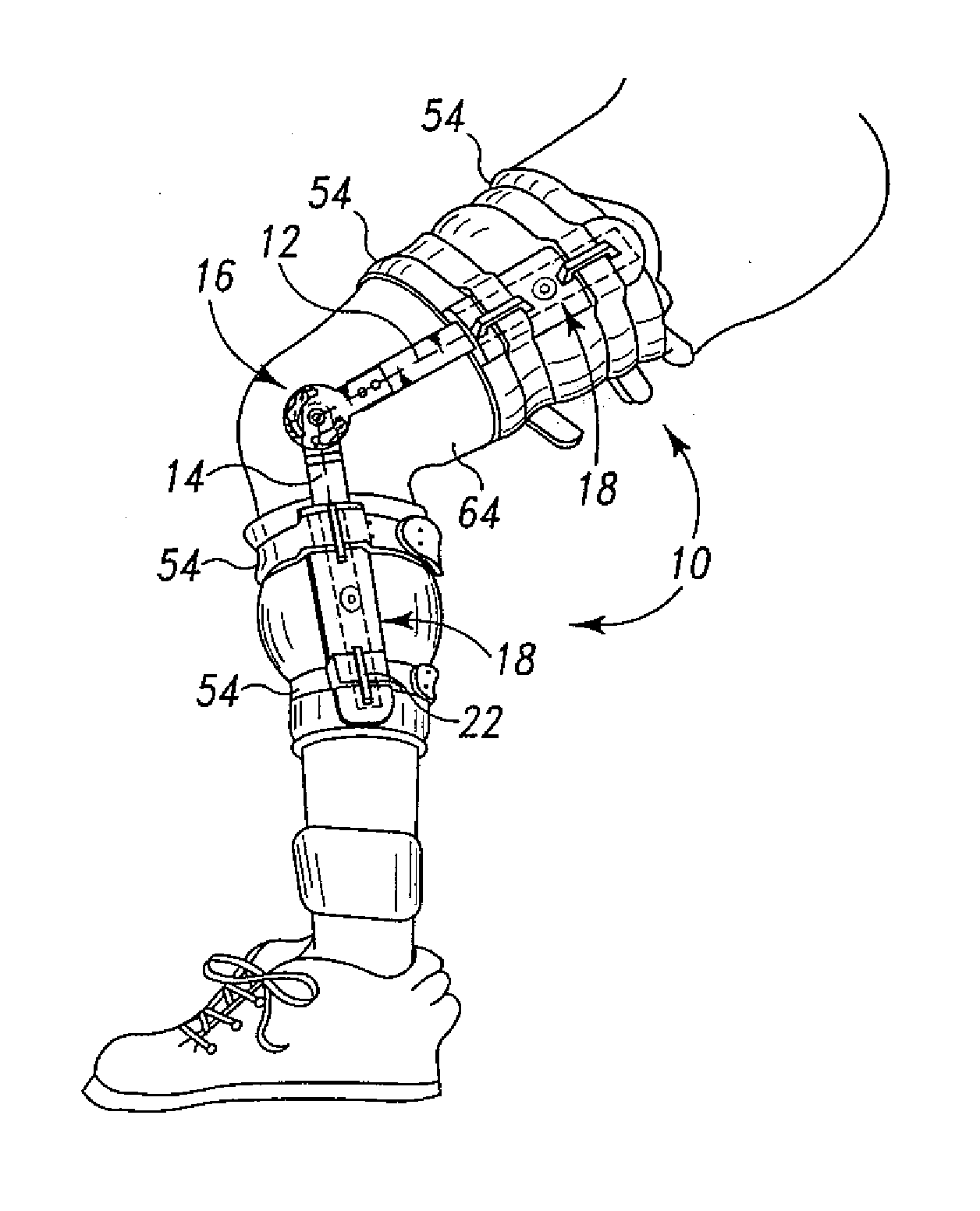
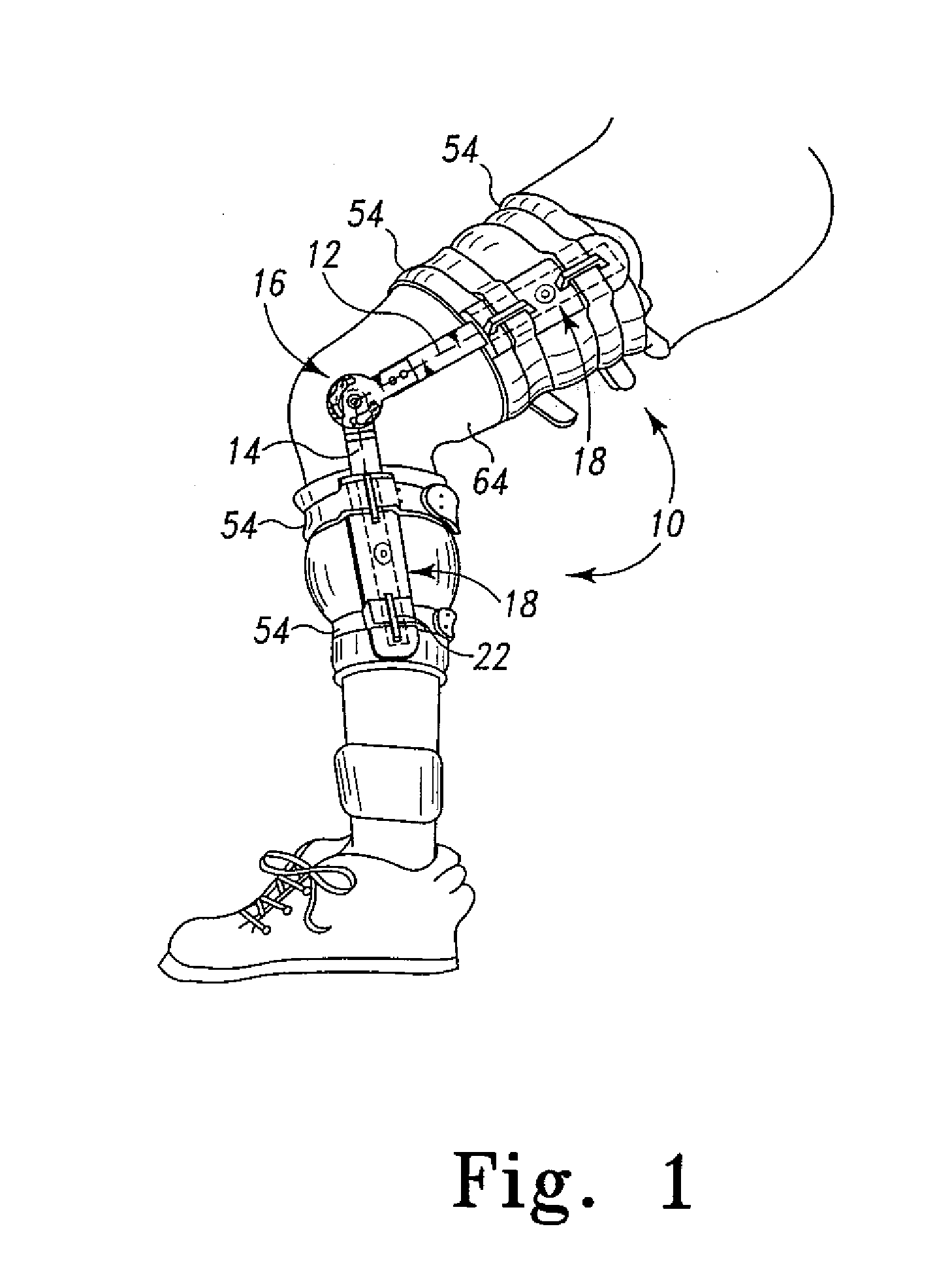
[0028] An orthopaedic brace 10 is shown in Fig. 1 operatively attached to a leg 64 using a plurality of straps 54 mounted on an upper strut 12 and a lower strut 14 with a hinge assembly 16 disposed between the upper strut 12 and the lower strut 14. While only one side of the orthopaedic brace 10 is shown (i.e. the hinge assembly 16, the upper strut 12, and the lower strut 14 or “assembly”) it should be understood that an identical, but mirror image, assembly is provided on the opposite side of the leg 64.

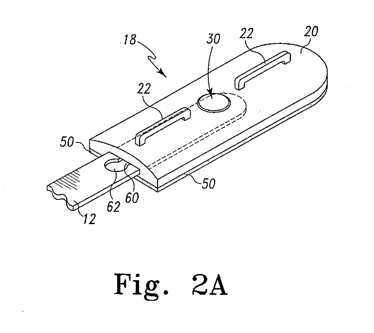
[0029] Each strut 12 and 14 is provided with a preferably identically configured wing assembly 18 although variations in either are contemplated, which is slidably mounted for adjustable movement on the elongated struts 12 and 14. Stated in another mann...


PUM


Abstract

Abstract of the Disclosure
An orthopaedic brace includes a strut length adjustment assembly to change the operable length of the strut for sizing the brace on a patient without the need for special tools or cutting of the strut. The adjustment assembly includes a biased adjustment mechanism that coacts with a plurality of notches in the strut to variably set/position the strut relative to the adjustment assembly to set the struts length. Each upper and lower strut preferably includes a strut length adjustment assembly to independently set the length of each strut. The strut length adjustment assembly retains a strut and includes a strap retention mechanism that is configured to releasably engage the strap.

Description

Detailed Description of the InventionRelated Applications[0001] The present application is a continuation of application Serial No. 09 / 608,940, filed on June 30, 2000, now Patent No. 6,383,156, issued May 7, 2002, which claims priority to provisional application Serial No. 60 / 156,342, filed on September 27, 1999. The complete disclosures of these applications are hereby expressly incorporated by reference.Field of the Invention[0002] The present application relates to orthopaedic braces adapted with an adjustable-length strut for use in stabilizing a joint after invasive surgery.Description of the Related Art[0003] In order to ensure the proper healing of a human joint after an injury or invasive surgery, it is often desirable to limit the pivotal motion of the human joint to a predetermined angular range between full extension and full flexion. The pivotal motion may be limited by a range of motion hinge disposed between an upper strut and a lower strut. In order for the ortho...

Claims


Application Information

Patent Timeline
Patent Type & Authority Applications(United States)
IPC IPC(8): A61H1/02A61F5/01
CPCA61F5/0125
Inventor ENZERINK, ROBERT-JANFINKES, JAMES GREGORYTELLES, JEFFREY LEE
Owner DJO
Why Eureka
Try Eureka