Programmable electricity consumption monitoring system and method

a technology of programmable electricity consumption and monitoring system, which is applied in the direction of electric controllers, instruments, analysing/displaying, etc., can solve the problems of reducing power consumption and difficult for the average consumer

Active Publication Date: 2005-03-17
ELMO CORP
View PDF27 Cites 104 Cited by
  • Summary
  • Abstract
  • Description
  • Claims
  • Application Information

AI Technical Summary

Benefits of technology

The Receiving Display Unit can also be linked to one or more load shedding devices using power line carrier technology connections via existing power lines. The load shedding device is then connected to at least one household or business appliance

Problems solved by technology

Reducing power consumption, though advantageous for the public as a whole

Method used


Image

  • Programmable electricity consumption monitoring system and method
  • Programmable electricity consumption monitoring system and method
  • Programmable electricity consumption monitoring system and method

Examples


embodiment 40

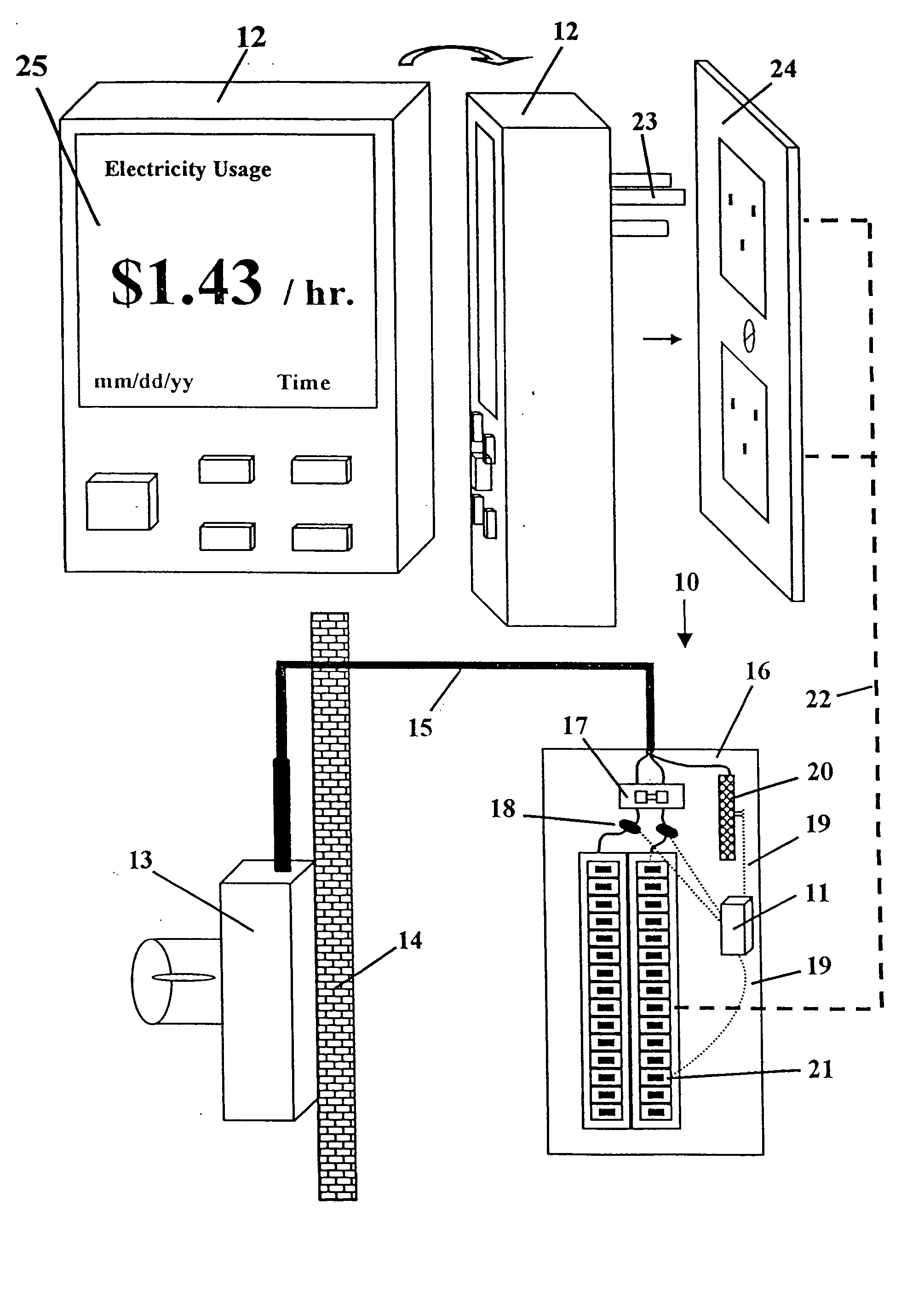
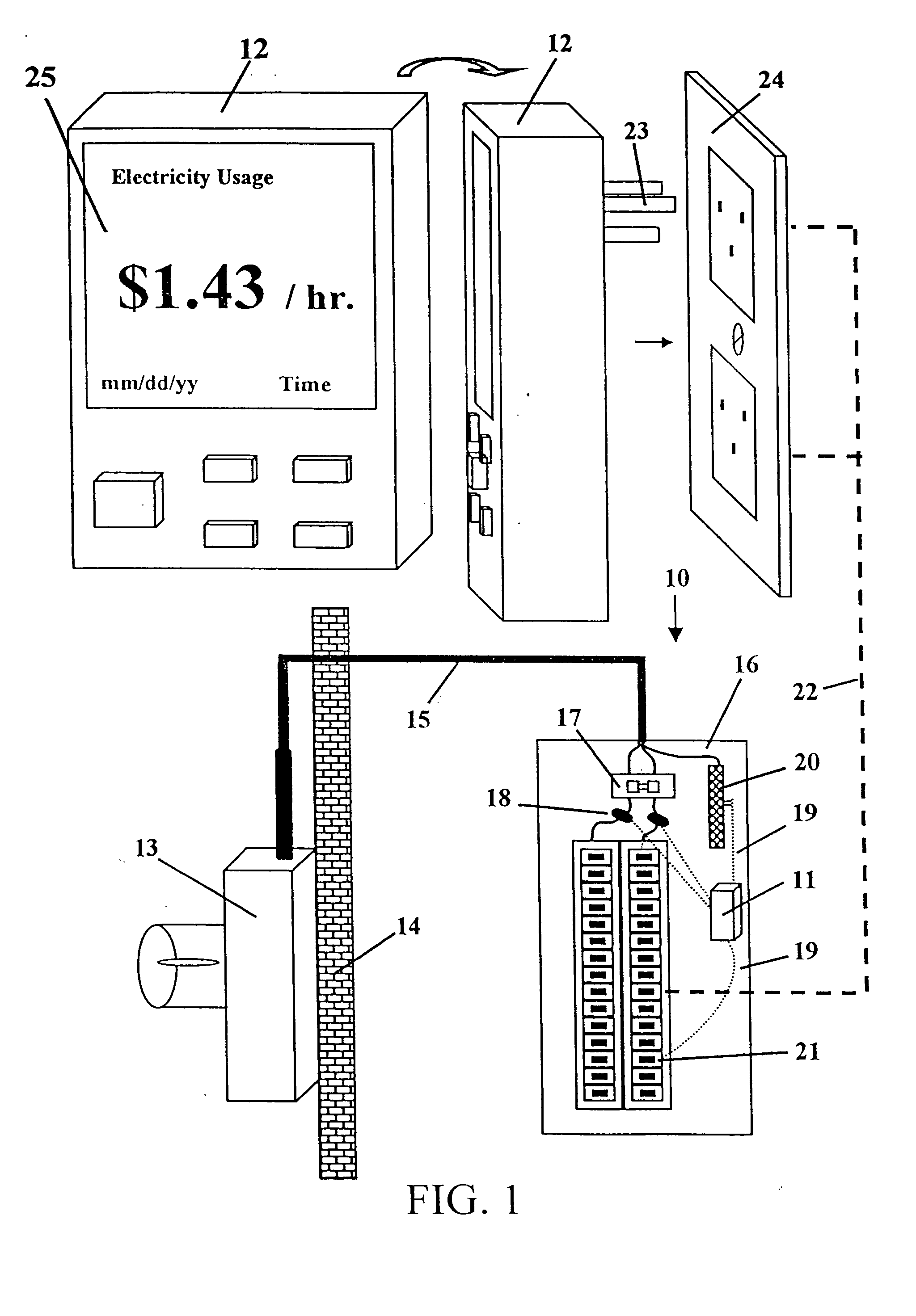
As shown in the electricity consumption device embodiment 40 illustrated in FIG. 6, a Measuring Transmitting Unit 41 is connected to current sensing modules 42 in the main circuit breaker 43 within the consumer's circuit breaker panel box 44. Main service power lines 45 extend between the main circuit breaker 43 and a utility meter 46 and back to the utility supply 47. Preferably, each current sensing module 42 includes a permanently wired burden resistor in the Measuring Transmitting Unit to preclude the possibility of large open circuit voltages associated with open circuit current transformers. The Measuring Transmitting Unit sums the analog signals, performs an analog-to-digital conversion, and then encodes the digital signal and transmits the encoded signal over existing power wiring within the home or other building using power line carrier transmission technology. Once installed, the Measuring Transmitting Unit will function indefinitely until removed.

With the Measuring Tran...

embodiment 63

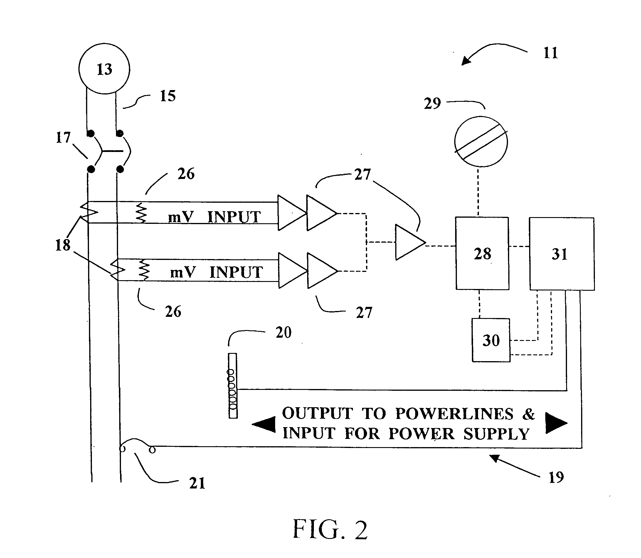
10 electricity monitoring system 11 Measuring Transmitting Unit (MTU) 12 Receiving Display Unit (RDU) 13 utility KWH meter 14 outside wall 15 main service power circuit 16 circuit breaker panel 17 main circuit breaker 18 current transformers 19 MTU power wires 20 neutral bus bar 21 individual circuit breakers 22 existing power wiring 23 power plug 24 120 V AC wall receptacle 25 display 26 burden resistors 27 amplifiers 28 MTU microcontroller 29 service size selector switch 30 MTU power supply 31 MTU power line carrier transmission interface controller (transmit) 32 RDU power supply 33 RDU power line carrier transmission interface controller (transmit and receive) 34 data decoder / encoder 35 RDU microcontroller 36 input and mode buttons 37 alarm 38 program and data RAM, PROM, EPROM, and EEPROM memory 40 alternate embodiment of electricity monitoring system 41 MTU 41A MTU add-on unit 42 current sensing modules 43 main circuit breaker 44 circuit breaker panel box 45 main power lines 46 ...


PUM


Abstract

A programmable system for monitoring electricity consumption by a residence or business, including: (a) a Measuring Transmitting Unit integrated in a main circuit breaker or utility meter in the residence or business; comprising: (1) a means of receiving AC analog signals, converting the AC analog signals to DC analog signals, summing the DC analog signals, and outputting the information; (2) a microcontroller; (3) a power line carrier transmission interface controller; and (4) a power supply for powering the Measuring Transmitting Unit; and (b) a programmable Receiving Display Unit, comprising: (1) a power supply for powering the Receiving Display Unit; (2) a power plug; (3) a power line carrier transmission interface controller; (4) a data decoder; (5) a microcontroller; (6) memory associated with the microcontroller; (7) a visual display; and (8) a mechanism for inputting to the Receiving Display Unit; and wherein the Measuring Transmitting Unit translates current to digitally encoded signals, and transmits the signals over existing power circuits in the residence or business; and the Receiving Display Unit receives the signals, decodes them, and translates them for viewing. A method for monitoring electricity consumption by a residence or business is also included.

Description

BACKGROUND OF THE INVENTION 1. Technical Field The present invention refers to a system and method for monitoring energy usage, preferably a system for continuously measuring and displaying electrical power consumption and cost at a consumer's residence or business. 2. Background Information Our society recognizes its dependence upon electricity for day to day living, as well as the need to develop alternate forms of energy. Reducing power consumption, though advantageous for the public as a whole as well as the private individual, is difficult for the average consumer. The average consumer only receives feedback regarding power consumption upon receipt of a monthly bill from the power company. A need exists for a practical, programmable, user friendly, affordable, portable system for continuous, contemporaneous monitoring of power consumption; a system that is integral with a main circuit breaker or utility meter and can easily be installed by a contractor or builder in the re...

Claims


Application Information

Patent Timeline
IPC IPC(8): G01D4/00G01R22/00H02J13/00
CPCG01D4/006G01R22/00Y02B90/243Y04S20/40Y04S20/46Y02B90/245Y04S20/325Y04S20/30G01D2204/18Y02B90/20
Inventor RODENBERG, ERNEST ADOLPH IIIBORDEN, ROBERT RICHARD
Owner ELMO CORP
Why Eureka
Try Eureka