
Method for real-time instruction information tracing

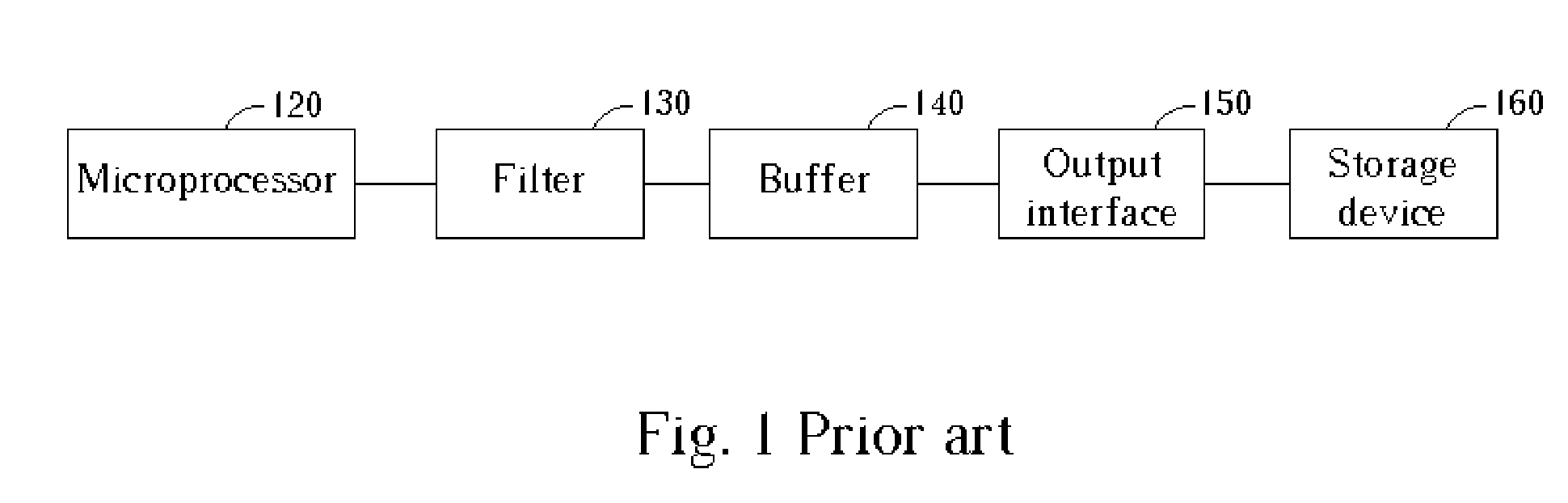
a technology of instruction information and real-time instruction, which is applied in the direction of program control, computation using denominational number representation, instruments, etc., can solve the problems of increasing hardware cost, affecting the performance of the output interface, and the capacity of the buffer b>140/b> is often not capable of recording instruction information about every instruction in the entire program, so as to reduce hardware cost and buffer capacity. the effect of bandwidth and reducing hardware cos

Inactive Publication Date: 2005-03-17
NOVATEK MICROELECTRONICS CORP
View PDF10 Cites 34 Cited by
  • Summary
  • Abstract
  • Description
  • Claims
  • Application Information

AI Technical Summary

Benefits of technology

The invention provides a method for real-time instruction tracing with lower hardware cost. The method keeps track of specific instructions executed by a microprocessor and records the information about them in a buffer. When the buffer becomes full, the method stops the program and outputs the recorded information via an output interface. The method uses a trigger count value to control the tracing flow and allows for real-time tracing without interrupting the program. The invention reduces the demand on the buffer and output interface capacity, resulting in lower hardware cost.

Problems solved by technology

In other words, the bugs happen only when there are no interruptions caused by tracing operations when the microprocessor runs the whole program.
However, the capacity of the buffer 140 is often not capable recording the instruction information about every instruction in the entire program.
Meaning, the primary drawback of the prior art is that the buffer and output interface that fit the above conditions will result in increased hardware cost.

Method used


Image

  • Method for real-time instruction information tracing
  • Method for real-time instruction information tracing
  • Method for real-time instruction information tracing

Examples


Embodiment Construction

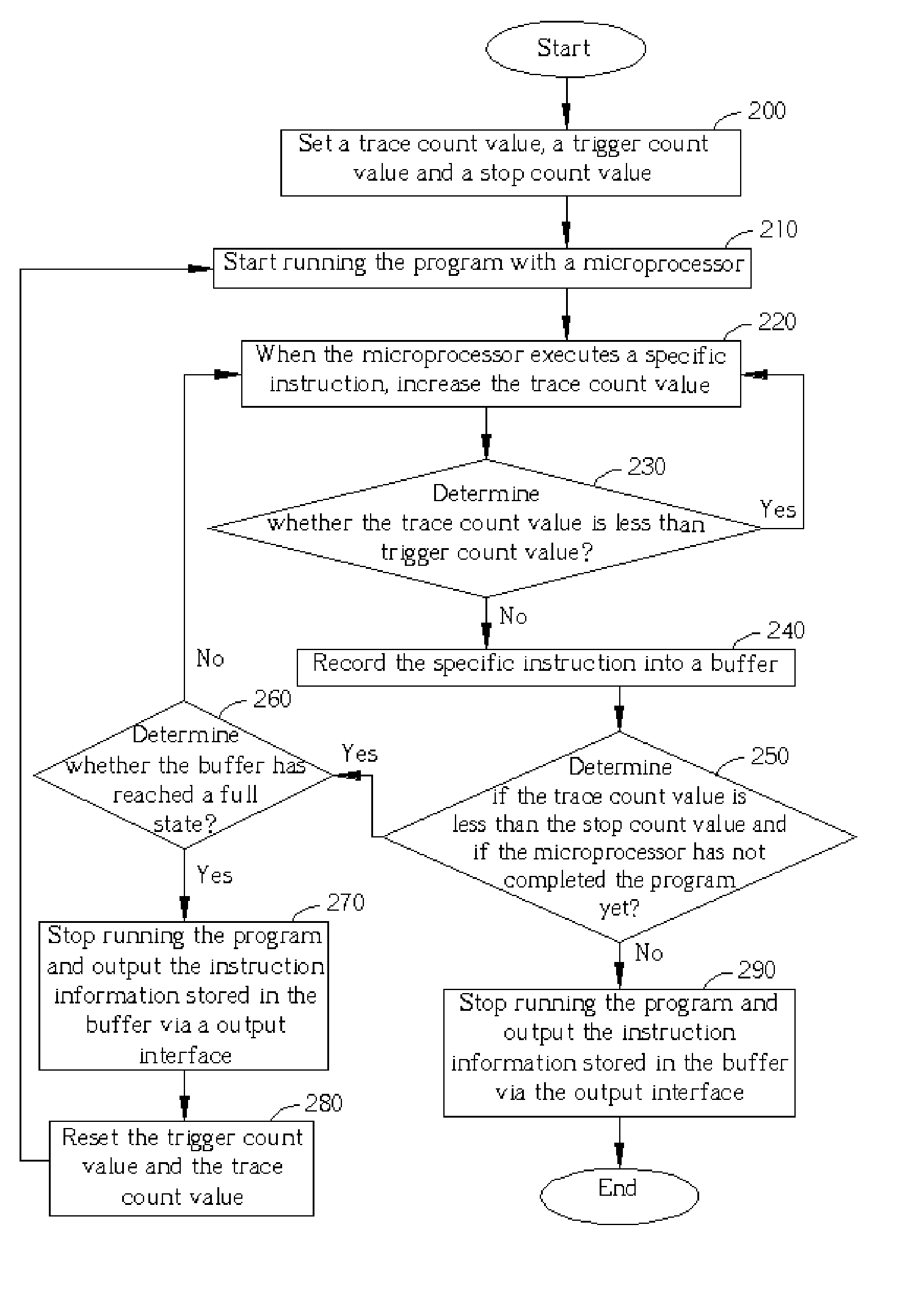
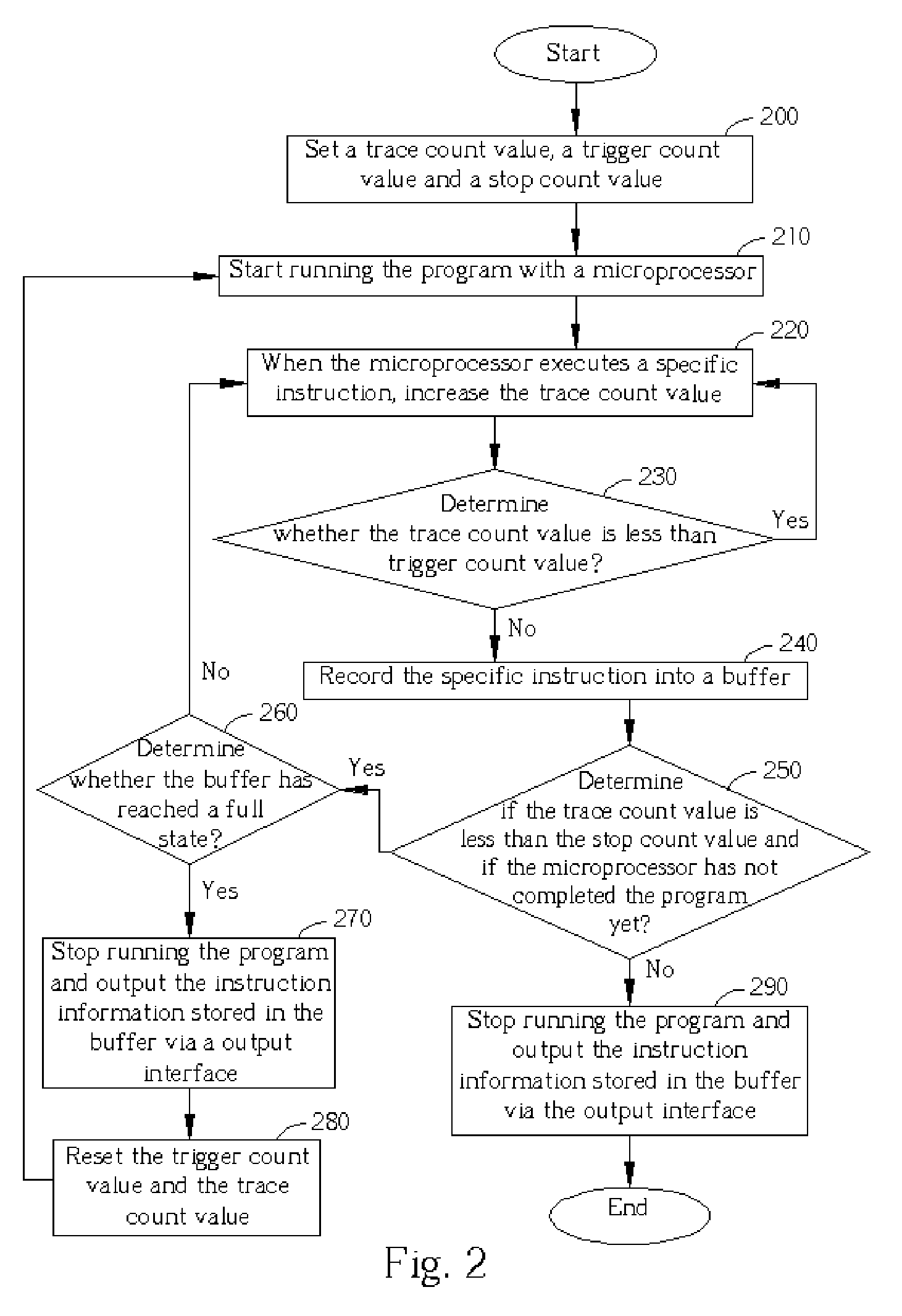
[0017] Please refer to FIG. 2. FIG. 2 is a flowchart of the real-time instruction tracing according to the present invention. The flow shown in FIG. 2 is used for recording the information about a plurality of specific instructions within a program executed by a microprocessor from a tracing start point in the running history. The steps of FIG. 2 will be described in detail as follows:

[0018] Step 200: Set the trace count value to an initial value; set the trigger count value according to the desired start point of tracing; set the stop count value according to the desired stop point of tracing.

[0019] Step 210: Start running the program from the beginning with the microprocessor.

[0020] Step 220: Increase the trace count value when an instruction is executed by the microprocessor.

[0021] Step 230: If the trace count value is less than the trigger count value, go back to the step 220. Otherwise, go to the step 240.

[0022] Step 240: Record the instruction information about the specif...


PUM


Abstract

A method for real-time instruction information tracing for recording the information about a plurality of specific instructions executed by a processor from a tracing start point in the history of running a program, wherein the program contains the specific instructions. The method contains the following step.A trace count value is set to an initial value. A trigger count value is set according to the tracing start point. The processor starts running the program. The trace count value is increased whenever a specific instruction executed by the processor. If the increased trace count value is equal to or larger than the trigger count value, record the instruction information about the specific instruction executed by the processor in a buffer; if the buffer is full, stop running the program and output the instruction information stored in the buffer via an output interface. During this time reset the trigger count value according to the trace count value, reset the trace count value as the initial value, and then start running the program with the processor again. When the processor has finished running the program, output the instruction information stored in the buffer via the output interface.

Description

BACKGROUND OF INVENTION [0001] 1. Field of the Invention [0002] The invention relates to real-time instruction information tracing, and more particularly, to a method for recording instruction information of specific instructions executed by a microprocessor while the microprocessor runs a program. [0003] 2. Description of the Prior Art [0004] In order to debug a program while a microprocessor runs the program, an instruction tracing technique is commonly used. The instruction tracing technique is used for tracing and recording instruction information of some specific instructions executed by the microprocessor while the microprocessor runs the program. The instruction information can be of various forms, such as a memory address storing the specific instruction or a controlling code of the specific instruction. What kind of instruction information that needs to be recorded depends on debugging demands. [0005] Some bugs only occur when the microprocessor executes the whole program b...

Claims


Application Information

Patent Timeline
Patent Type & Authority Applications(United States)
IPC IPC(8): G06F7/38G06F9/44
CPCG06F11/3636
Inventor WANG, YU-MIN
Owner NOVATEK MICROELECTRONICS CORP
Learn More