Reflecting surface antenna double-beam forming design method

A design method and reflective surface technology, applied in antennas, antenna grounding switch structural connections, electrical components, etc., can solve antenna beam gain loss, poor performance of antenna beam suppression area, unable to meet antenna design requirements, and reduce technical advantages of reflective surfaces and other issues, to achieve the effect of facilitating compact antenna design, facilitating engineering applications, and improving coverage efficiency or gain

Active Publication Date: 2017-02-22
XIAN INSTITUE OF SPACE RADIO TECH
View PDF4 Cites 15 Cited by
  • Summary
  • Abstract
  • Description
  • Claims
  • Application Information

AI Technical Summary

Problems solved by technology

If the existing design methods are used directly for dual-beam design, it is impossible to achieve a dual-beam antenna that is close to the performance of an independent antenna, and there are problems such as low radiation beam efficiency and poor beam coverage matching, and the obtained antenna beam gain loss is obvious or the antenna beam Poor performance of the suppression zone (or sidelobe) does not meet the expected antenna design requirements, reducing the technical advantage of the dual-beam design of the reflector

Method used


Image

  • Reflecting surface antenna double-beam forming design method
  • Reflecting surface antenna double-beam forming design method
  • Reflecting surface antenna double-beam forming design method

Examples


Embodiment

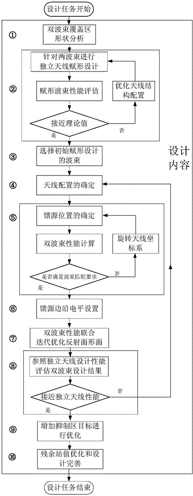
[0051] For the dual-beam coverage application of geosynchronous communication satellites, its dual-beam shape characteristics are nothing more than two relationships: "similar" and "different". One of the beams is in the sub-satellite point area, and the two beams deviate from the sub-satellite point area. For the former case, the Z-axis rotation of the antenna system coordinate system that may be used in the method will point to the sub-satellite point as the axis, while for the latter case, the reflecting surface points to one of the beam centers, and the antenna system coordinates The Z-axis rotation of the system will take the center of the beam as the axis.

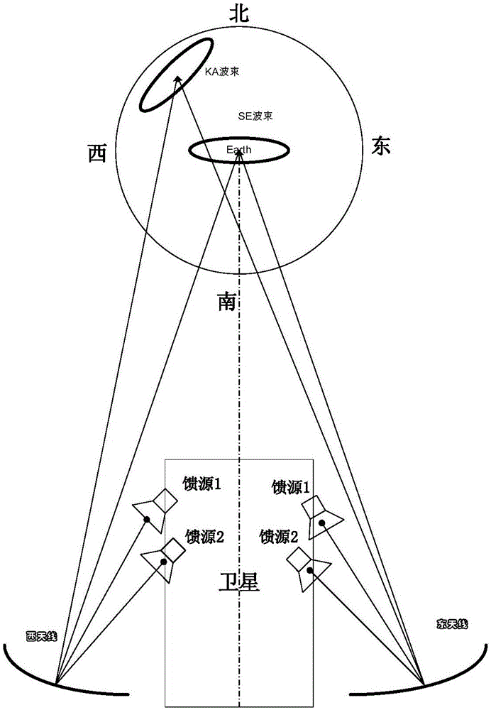
[0052] here to Figure 4 The dual-beam coverage map in is an example according to the content of the present invention, using Figure 5 The configuration of the antenna structure is used to describe the implementation of the method.

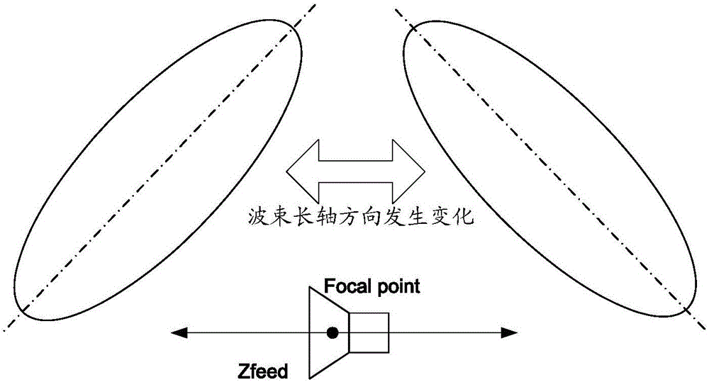
[0053] Step 1: It is found that the long axes of the KA beam and the SE beam in ...


PUM


Abstract

The invention provides a reflecting surface antenna double-beam forming design method. Through creatively introducing a double-beam covering area shape characteristic analyzing step in a designing process, a targeted initial beam acquiring manner and a corresponding antenna structure configuration strategy are made. Based on searching of a reflection plane scattered field focusing point under planar wave excitation according to a conjugate field matching theory, a rotation rule in long axis direction of a longitudinal movement beam of feed sources at two sides of a focusing point is utilized, and wave beam covering matching design is performed. Through feed source position adjustment, axial torsion of the whole reflection surface antenna system is performed, thereby improving beam covering matching property of double beams and performance of a restraining area, and furthermore improving gain of a double-beam coverage area after optimization. According to the reflecting surface antenna double-beam forming design method, according to a wave beam shape characteristic relationship, antenna layout and the like, and design principles such as a wave beam shape is adjusted according to the feed source position. A design order, a parameter selecting principle and technical details in double-beam design are described, and gain improvement of the double-beam coverage area is realized.

Description

technical field [0001] The invention belongs to the technical field of microwave antennas, and relates to an antenna design method, in particular to an antenna design method capable of improving the gain (or antenna efficiency) of a dual-beam forming coverage area with a special beam relationship. Background technique [0002] With the continuous deepening of the application of satellite communication technology, more and more payload functions are required for satellites, and the demand for antenna integration is also increasing. For communication satellites, it is often desired to achieve more beam coverage under the constraints of limited spectrum resources and limited antenna layout, that is, to use a limited number of antennas to achieve as many beams as possible. The dual (multiple) beam design technology of the reflector provides a possibility to realize the same frequency beam covering different areas in one antenna, and the performance of the two beams is close to t...

Claims


Application Information

Patent Timeline
Patent Type & Authority Applications(China)
IPC IPC(8): H01Q15/14H01Q19/10H01Q3/00H01Q3/02H01Q3/08H01Q1/50
CPCH01Q1/50H01Q3/00H01Q3/02H01Q3/08H01Q15/14H01Q19/10
Inventor 张明涛张新刚张坚弓金刚时政新宋文超
Owner XIAN INSTITUE OF SPACE RADIO TECH
Why Eureka
Try Eureka