
Multi-stage eductor apparatus

a multi-stage, eductor technology, applied in mechanical equipment, machines/engines, transportation and packaging, etc., can solve problems such as substantial performance reduction, and achieve the effect of effective us

Inactive Publication Date: 2005-03-24
FORET PLASMA LABS
View PDF32 Cites 73 Cited by
  • Summary
  • Abstract
  • Description
  • Claims
  • Application Information

AI Technical Summary

Benefits of technology

The present invention provides an eductor apparatus that overcomes the drawbacks inherent in fixed ratio eductors,and which can be effectively used over a wide range of pressures and flow rates. The multi-stage eductor apparatus of the invention includes a first eductor
The structure and features of the eductor apparatus of the invention will be described in more detail with reference to the accompanying drawing figures.

Problems solved by technology

There are several drawbacks associated with eductors known in the prior art.
Eductors are designed to operate effectively within a relatively narrow range of driving fluid pressures and flow rates, and deviation from the design range typically results in substantially reduced performance.

Method used


Image

  • Multi-stage eductor apparatus
  • Multi-stage eductor apparatus
  • Multi-stage eductor apparatus

Examples


Embodiment Construction

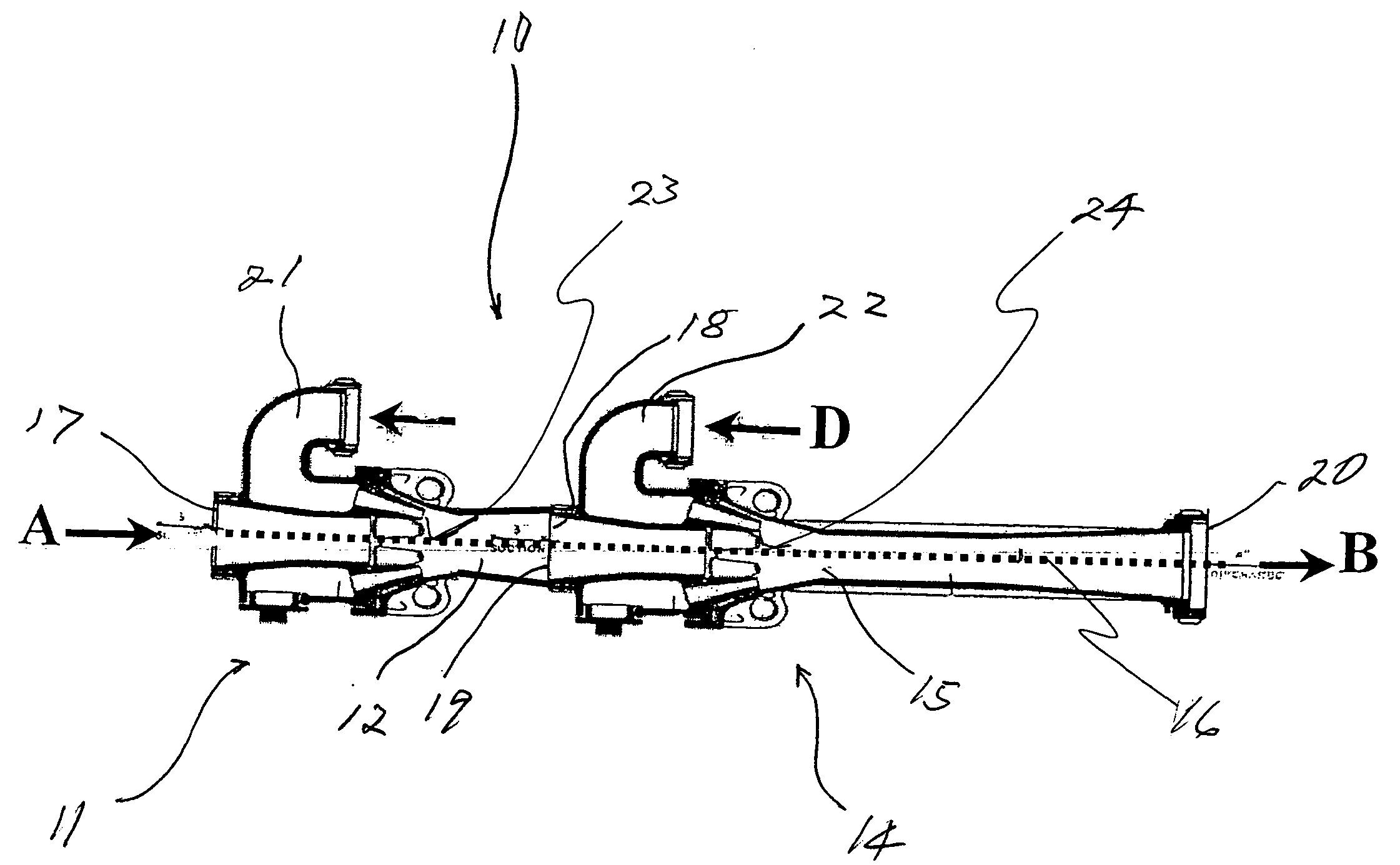
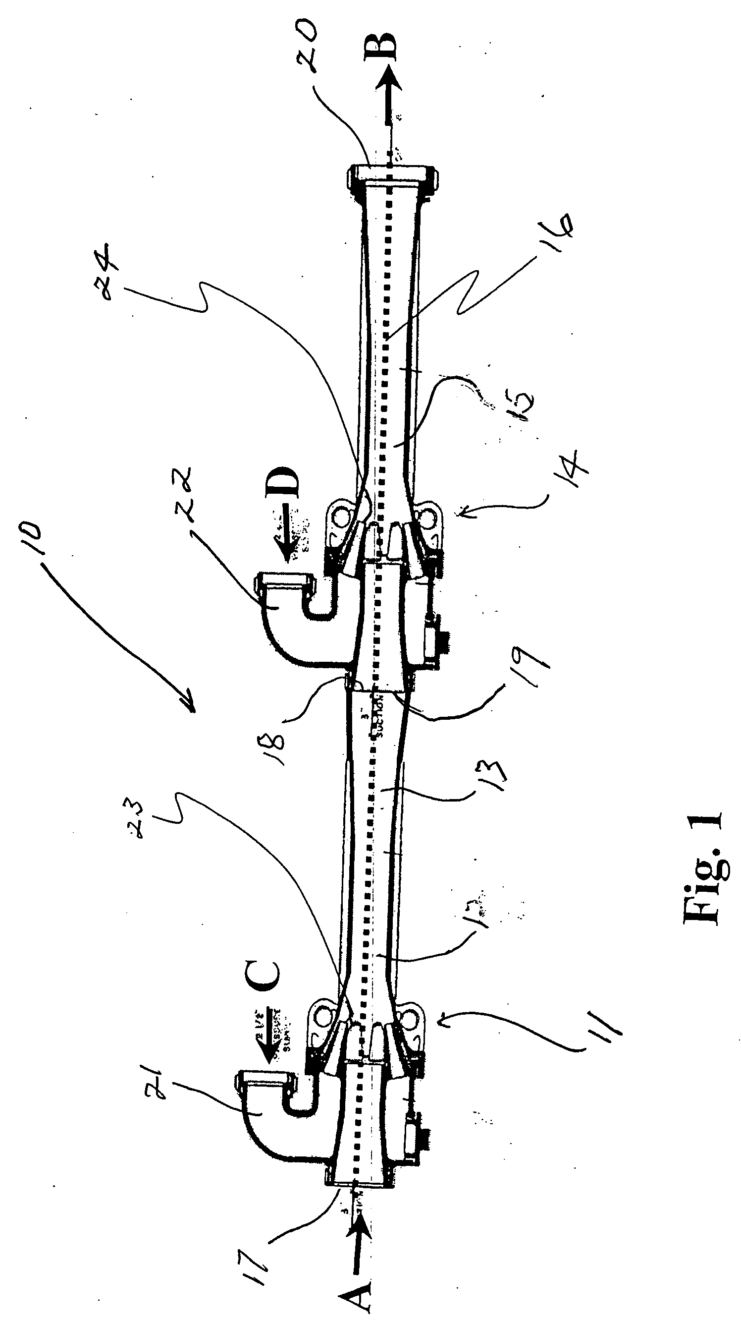
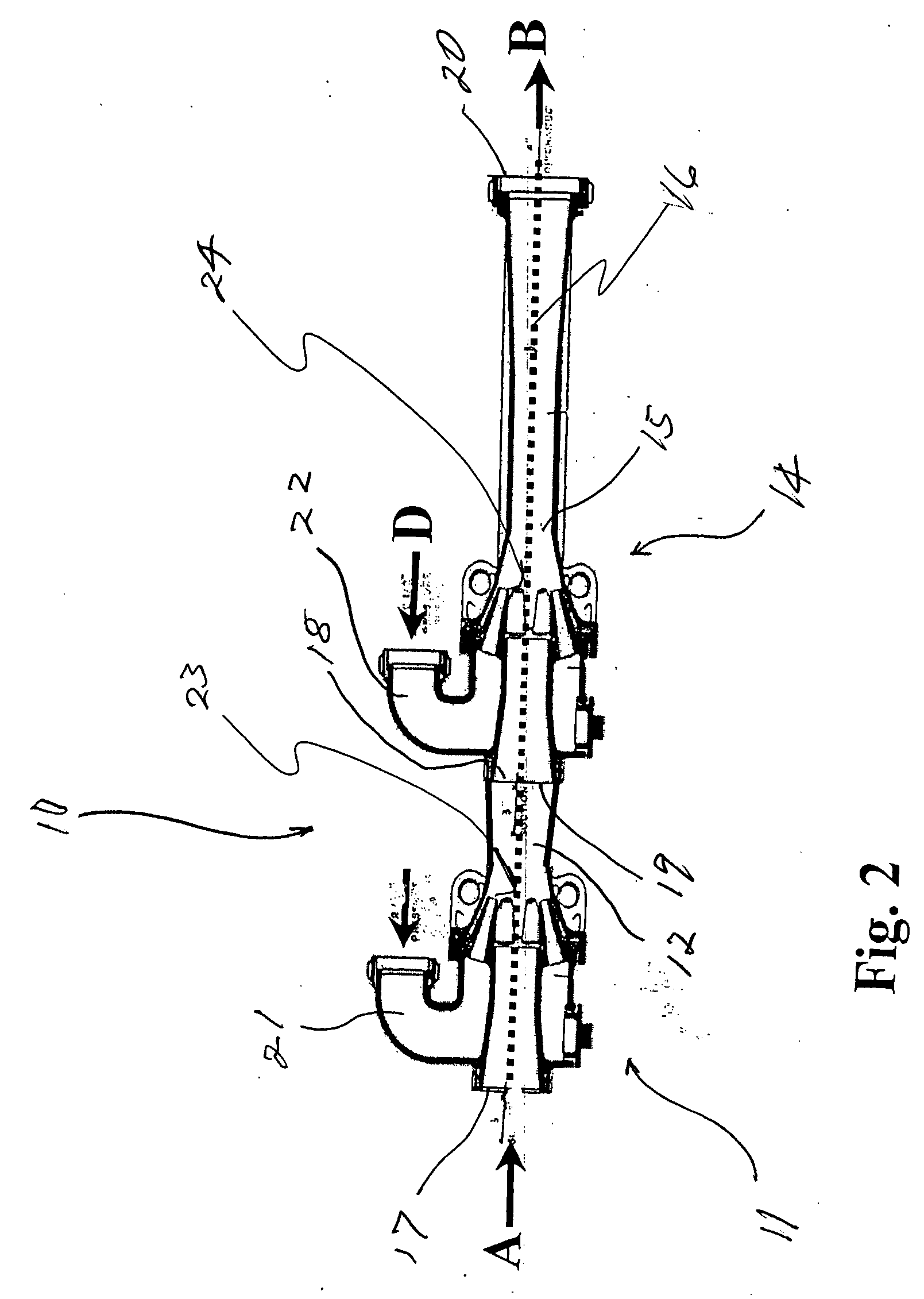
The multi-stage eductor of the invention, generally identified by reference number 10, comprises a first stage venturi-type eductor 11, with a venturi throat section 12 and a diffuser section 13, and a second stage venturi-type eductor 14 with a venturi throat section 15 and a diffuser section 16, connected in series with the first stage. The first stage eductor has an inlet 17 and an outlet 18, and the second stage eductor has an inlet 19 and an outlet 20. The inlet of the second stage structure connected to the outlet of the first stage so that the longitudinal axes of the first and second stages are in coaxial alignment. The flow of material into the multi-stage eductor apparatus is indicated as “A”, and the flow of material from the multi-stage eductor apparatus is indicated as “B”. The dashed line through the structure represents the longitudinal axis of the multi-stage eductor, as well as the center line of the flow path of material drawn into and through the eductor.

The fi...


PUM


Abstract

A multi-stage eductor apparatus includes a first stage eductor with an inlet, an outlet, and a venturi throat between the inlet and outlet into which a driving fluid is injected to flow from the outlet and create a suction at the inlet for drawing material into the inlet and through the first stage eductor with the driving fluid, and at least a second stage eductor of the same or similar configuration, with the inlet of the second stage eductor connected directly to the outlet from the first stage eductor, thereby increasing the suction at the inlet to the first stage eductor and maintaining the suction at the inlet to the first stage eductor through a wide range of driving fluid flow rates.

Description

FIELD OF THE INVENTION The present invention generally relates to venturi-type suction devices and apparatus, and in its preferred embodiments more specifically relates to suction and mixing eductor devices and apparatus utilizing a plurality of longitudinally aligned stages. BACKGROUND OF THE INVENTION The venturi tube, which invented by Giovanni Venturi, basically comprises two tapered sections of pipe joined by a narrow throat. This convergent-divergent shape is commonly referred to as a diffuser when used in venturi tubes. As a fluid flows through the venturi tube structure the fluid velocity in the throat is increased and the pressure is reduced, in keeping with the principles of conservation of energy and with Bernoulli's Theory, which states, “At any point in a pipe through which a fluid is flowing the sum of the pressure energy, the kinetic energy, and the potential energy of a given mass of the fluid is constant.” Over time it was realized that the reduced pressure sectio...

Claims


Application Information

Patent Timeline
Patent Type & Authority Applications(United States)
IPC IPC(8): F04F5/00F04F5/04F04F5/12F04F5/22F04F5/26F04F5/46
CPCF04F5/467F04F5/04Y10T137/87587
Inventor FORET, TODD L.
Owner FORET PLASMA LABS
Features
  • Generate Ideas
  • Intellectual Property
  • Life Sciences
  • Materials
  • Tech Scout
  • Unparalleled Data Quality
  • Higher Quality Content
  • 60% Fewer Hallucinations
Learn More