Integrated liquid cooling system for electrical components

Inactive Publication Date: 2005-03-24
HON HAI PRECISION IND CO LTD
View PDF7 Cites 24 Cited by
  • Summary
  • Abstract
  • Description
  • Claims
  • Application Information

AI Technical Summary

Benefits of technology

[0008] Another object of the present invention is to provide a liquid cooling system which can be readily installed or removed to or from an electrical enclosure.

Problems solved by technology

The traditional cooling means such as combined heat sinks and cooling fans are increasingly unable to provide satisfactory cooling performance.
Installation and removal of the cooling system can be troublesome and problematic.
In addition, a large space for receiving these discrete components is required.

Method used


Image

  • Integrated liquid cooling system for electrical components
  • Integrated liquid cooling system for electrical components
  • Integrated liquid cooling system for electrical components

Examples


Embodiment Construction

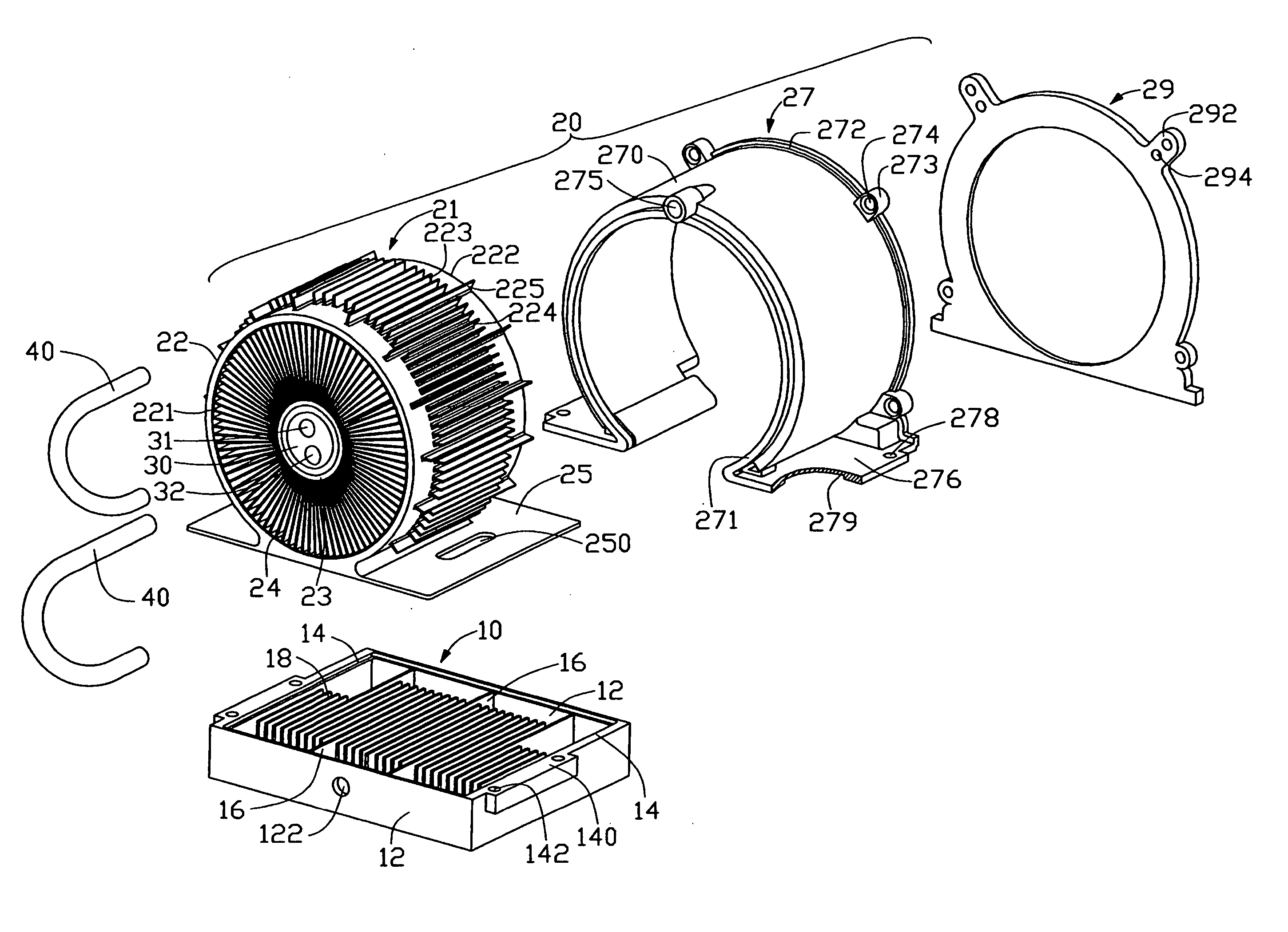
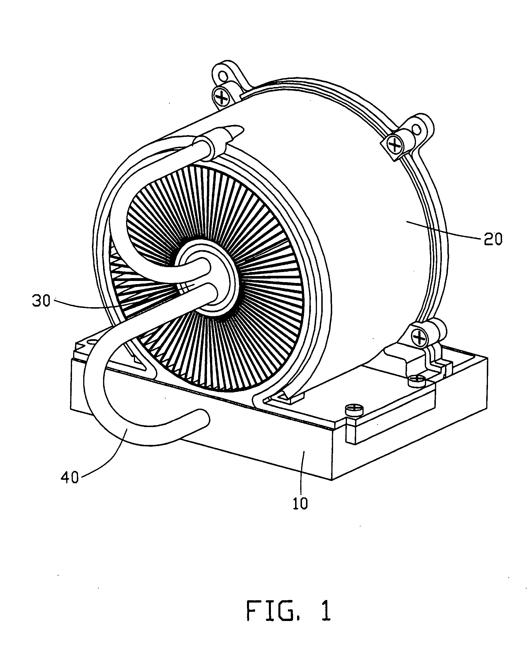
[0014]FIG. 1 illustrates a liquid cooling system in accordance with a preferred embodiment of the present invention. The liquid cooling system comprises a tank 10 containing liquid coolant therein, a heat dissipating unit 20 attached above the tank 10, a pump 30 located in the heat dissipating unit 20, and two pipes 40 connecting the pump 30 to the tank 10 and the heat dissipating unit 20 respectively.

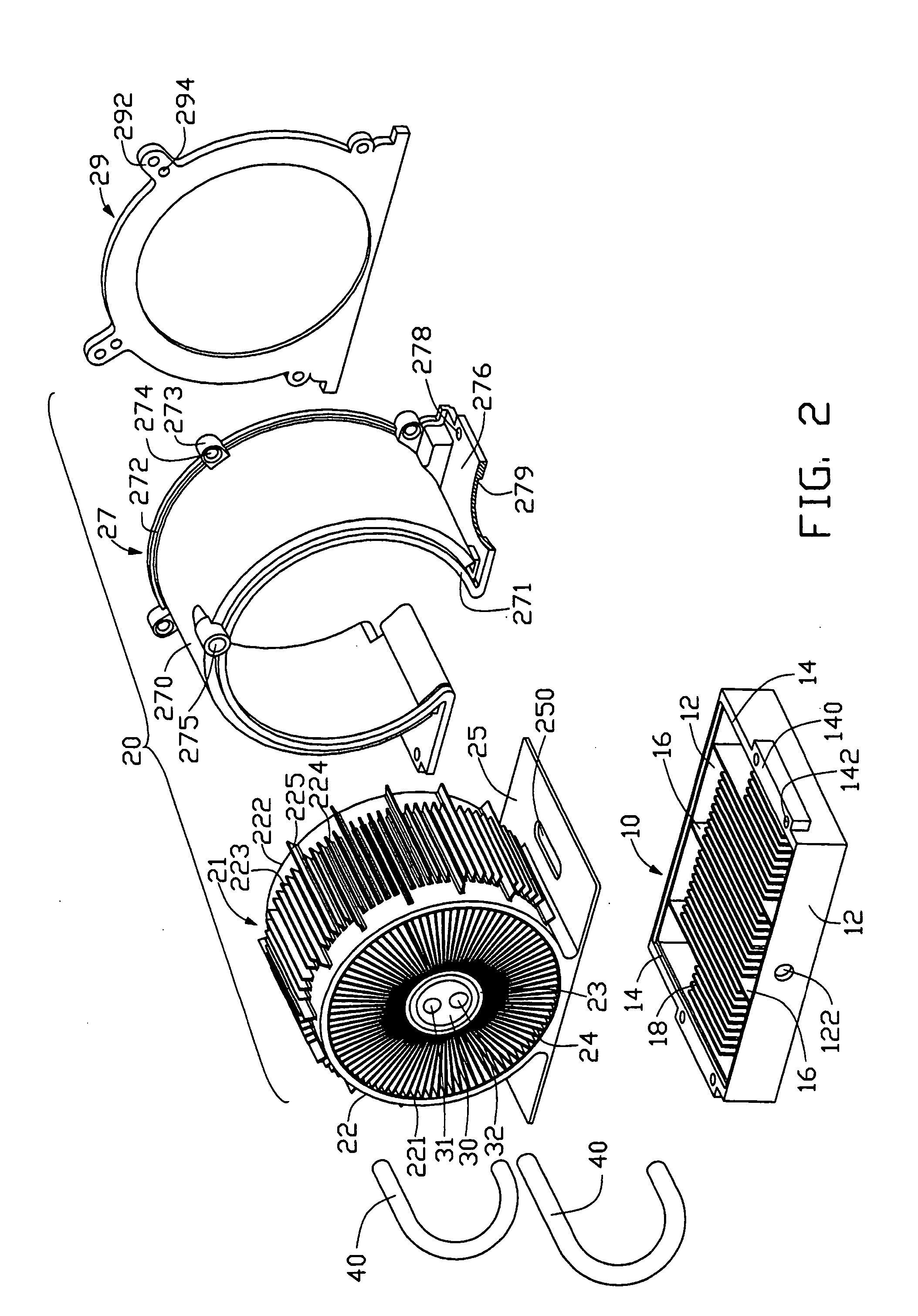
[0015] Referring to FIGS. 2 and 3, the tank 10 has a bottom base 11, for thermally contacting a heat generating component 100. Two pairs of sidewalls 12, 14 extend perpendicularly upwardly from the bottom base 11, whereby the tank 10 is substantially parallelepiped-shaped. In alternative embodiments of the present invention, the tank 10 can have other suitable shapes, such as be cylindrical. The bottom base 11, and the sidewalls 12, 14 cooperatively defines a cavity (not labeled) therebetween. An inlet 122 is defined in a middle of one sidewall 12, in communication with the cavity. A ...


PUM


Abstract

A liquid cooling system includes a tank (10) for thermally contacting a heat source (100), a cylindrical heat dissipating unit (20) mounted on the tank, and a pump (30) located within the cylindrical heat dissipating unit. The tank defines a cavity therein for containing liquid coolant for heat exchange, and an inlet (122) in communication with the cavity. The heat dissipating unit defines a chamber therein in flow communication with the cavity, and an outlet (275) in communication with the chamber. The pump has an entrance (31) in flow communication with the outlet, and an exit (32) in flow communication with the inlet, thereby the tank, the heat dissipating unit, and the pump together forming a loop for circulation the of liquid coolant.

Description

BACKGROUND OF THE INVENTION [0001] 1. Field of the Invention [0002] The present invention relates generally to cooling systems, and more particularly to a liquid cooling system for rapidly cooling an electrical component such as a Central Processing Unit (CPU). [0003] 2. Related Art [0004] With the continuing development of computer electronics technology, new electronic packages such as the latest CPUs can perform more and more functions. Heat generated by these modern electronic packages has increased commensurately. The heat must be removed from the CPUs to prevent them becoming unstable or being damaged. The traditional cooling means such as combined heat sinks and cooling fans are increasingly unable to provide satisfactory cooling performance. Under such circumstances, cooling system using liquid cooling technology is thus developed for cooling the CPUs. [0005] Chinese patent numbers 98248834.3 and 99210734.2 respectively disclose such a kind of cooling system. This kind of co...

Claims


Application Information

Patent Timeline
IPC IPC(8): F28F3/02F28F3/12H01L23/473
CPCF28F3/02F28F3/12H01L23/473H01L2924/0002H01L2924/00
Inventor LEE, HSIEH KUNLAI, CHENG-TIENZHOU, SHI WEN
Owner HON HAI PRECISION IND CO LTD
Why Eureka
Try Eureka