Power tool
a technology of power tools and power components, applied in the field of power tools, can solve the problems of large rebound force produced by the anvil upon impingement, damage to the speed reduction mechanism portion, so as to achieve the effect of enhancing durability
- Summary
- Abstract
- Description
- Claims
- Application Information
AI Technical Summary
Benefits of technology
Problems solved by technology
Method used
Image
Examples
first embodiment
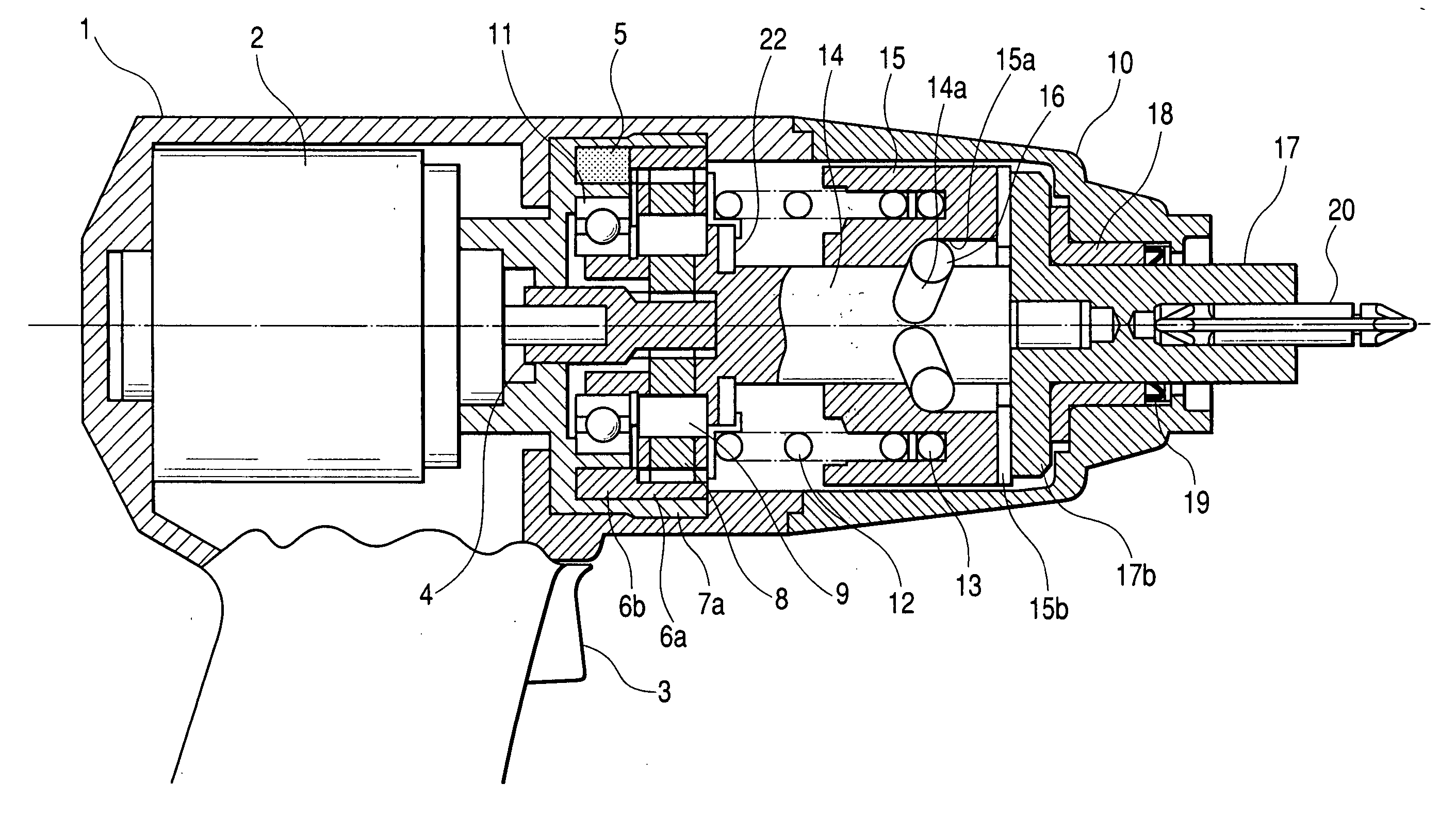
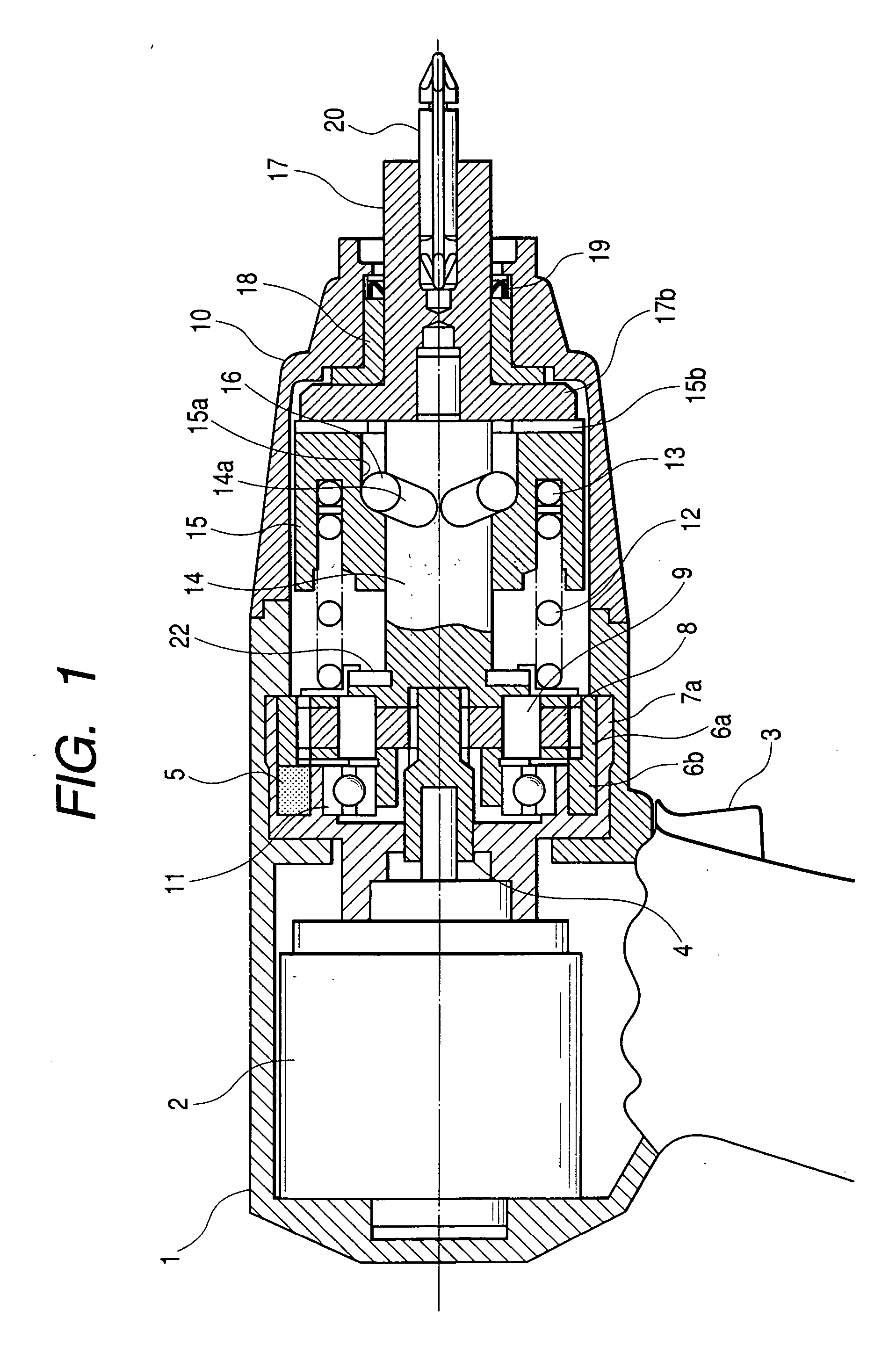
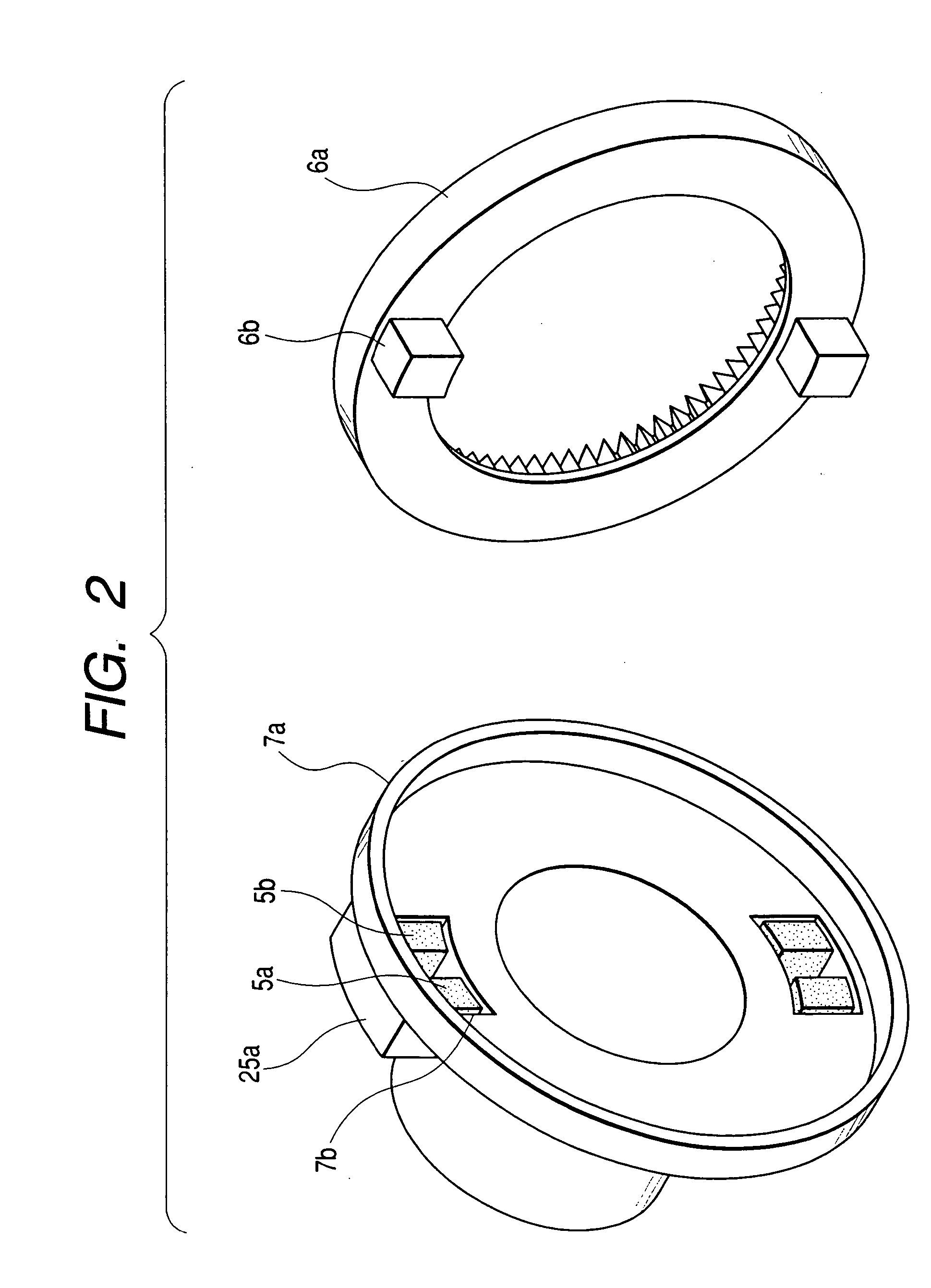
[0017] An impact tool of this embodiment will now be described with reference to FIGS. 1 to 6. FIGS. 1 and 2 show a first embodiment, and FIG. 1 is a partly-omitted, vertical cross-sectional, side-elevational view showing the impact tool, and FIG. 2 is an exploded view showing an impact damping mechanism mounted on the impact tool. In FIGS. 1 and 2, a motor 2, serving as a drive source, a speed reduction mechanism portion 8 for transmitting a rotational power of a pinion 4 which is an output shaft of the motor 2, a spindle 14 for transmitting the rotational power from the speed reduction mechanism portion 8, a hammer 15, which is rotatable and movable in a direction of the axis of rotation through steel balls 16 inserted in cam grooves 14a formed in the spindle 14, an anvil 17, having anvil claws 17b which are struck by a plurality of hammer claws 15b, provided at the hammer 15, to be rotated, an end tool 20, releasably attached to the anvil 17, and a spring 12, normally urging the ...
second embodiment
[0021]FIGS. 3 and 4 show a second embodiment, and FIG. 3 is a partly-omitted, vertical cross-sectional, side-elevational view showing an impact tool, and FIG. 4 is an exploded view showing an impact damping mechanism mounted on the impact tool. The impact damping mechanism is mounted on the impact tool shown in FIG. 3, and in this impact damping mechanism, projections 6d are formed on an outer surface of a fixed gear 6c as shown in FIG. 4, and holes 7d are formed respectively in those portions of a fixed gear support jig 7c (which is mounted within a housing 1) corresponding respectively to the projections 6d on the outer surface of the fixed gear 6c, and impact damping members 5c and 5d are inserted in these holes 7d.
[0022] In this impact damping mechanism, the fixed gear 6c is combined with the fixed gear support jig 7c in such a manner that the projection 6d of the fixed gear 6c is inserted between the impact damping members 5c and 5d. Therefore, the load is supported at a more ...
third embodiment
[0023]FIGS. 5 and 6 show a third embodiment, and FIG. 5 is a partly-omitted, vertical cross-sectional, side-elevational view showing an impact tool, and FIG. 6 is an exploded view showing an impact damping mechanism mounted on the impact tool. The impact damping mechanism is mounted on the impact tool shown in FIG. 5, and in this impact damping mechanism, a fixed gear 6 and a fixed gear support jig 7e are fixedly secured to each other as shown in FIG. 6, and impact damping members 5e and 5f are provided respectively on opposite sides of each of projections 7f which are rotation stoppers for preventing the rotation of the fixed gear support jig 7e relative to a housing 1.
[0024] In this impact damping mechanism, that side of each impact damping member 5e, 5f, facing in the same direction as the projection 7f, is held by a rib 1a of the housing 1 of the body, and besides the impact damping members 5e and 5f are provided between a bearing 11 and the housing 1, and therefore a rotational...
PUM
| Property | Measurement | Unit |
|---|---|---|
| speed | aaaaa | aaaaa |
| rotational power | aaaaa | aaaaa |
| force | aaaaa | aaaaa |
Abstract
Description
Claims
Application Information
 - R&D
- Intellectual Property
- Life Sciences
- Materials
- Tech Scout
- Unparalleled Data Quality
- Higher Quality Content
- 60% Fewer Hallucinations
Browse by: Latest US Patents, China's latest patents, Technical Efficacy Thesaurus, Application Domain, Technology Topic, Popular Technical Reports.
© 2025 PatSnap. All rights reserved.Legal|Privacy policy|Modern Slavery Act Transparency Statement|Sitemap|About US| Contact US: help@patsnap.com


