Paperboard container with bottom support

a technology of bottom support and paperboard, applied in the field of packaging, can solve the problems of limiting the interior space of the container, requiring excessive amounts of additional material, and reducing the strength of the reinforcement system, and achieve the effect of preventing sagging of the container bottom

Inactive Publication Date: 2005-03-24
INT PAPER CO
View PDF25 Cites 10 Cited by
  • Summary
  • Abstract
  • Description
  • Claims
  • Application Information

AI Technical Summary

Benefits of technology

[0008] The present invention comprises a container having a reinforcing cross beam or other rigid structure that extends across a bottom portion of the container and is operative to at least partially support product held in the container to prevent sagging of the container bottom.

Problems solved by technology

These supports, however, limit the interior space of the container and require excessive amounts of additional material.
However, these types of reinforcements are often bonded to the cover and do not come in significant contact with the side walls, lessening the strength of the reinforcement system.
Further, agricultural produce normally is packed in shipping containers in a cool damp environment, and tends to pool in the bottom of the container, causing the container bottom to sag.
Top reinforcements tend to obscure or impair the visibility of the product contained in the container unless they are removable.

Method used


Image

  • Paperboard container with bottom support
  • Paperboard container with bottom support
  • Paperboard container with bottom support

Examples


second embodiment

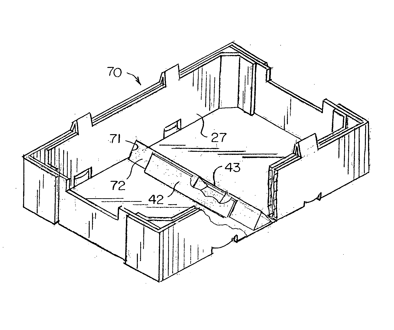
[0038] A second embodiment is shown at 70 in FIG. 7. This embodiment is similar to the embodiment of FIG. 2, except cut-outs 71 shaped complementally to the cross-sectional shape of the beam are made in the opposite inner side wall panels 27, forming recesses into which the opposite ends of an elongated beam 72 are inserted. Thus, in this form of the invention the beam is located and held in place both by the engagement of its opposite ends in the recesses, and by the adhesive attachment of the flaps to the top surfaces of the beam.

third embodiment

[0039] A third embodiment is shown at 80 in FIG. 8. In this embodiment, the container 81 is of simplified construction similar to the container shown in FIG. 1, but has the cuts 37, 38, and 39 (only some of which are shown) and scores 40 and 41, forming flaps 42 and 43 for adhesively attaching a cross beam (not shown) similarly to the FIG. 2 embodiment. In addition, crushed areas 82 are made in the inner facing surfaces of the opposite side walls 83, forming recesses into which the opposite ends of the beam (not shown) are inserted.

fourth embodiment

[0040] A fourth embodiment is shown at 90 in FIGS. 9 and 10. In this embodiment, the container is similar to the container of FIG. 2, but cross beam 91 is generally rectangular in transverse cross-sectional shape, with a flat top surface 92 extending generally parallel to the plane of the bottom wall 26. Cut-outs 93 shaped complementally to the cross-sectional shape of the beam are made in the opposite inner side wall panels 27 for receiving the ends of the cross beam, and modified flaps 94 and 95 are formed in the bottom wall for adhesive attachment to the beam. The flaps are defined by elongate transverse cut 37 and arched cuts 96 and 97 extending generally perpendicularly to each of the opposite ends of the cut 37, and longitudinally extending scores 98 and 99 extending between the outer ends of the arched cuts at opposite ends of the cut 37. It should be noted that the cuts do not necessarily have to be arched, such as for example they may be straight. Additional scores 100 and ...


PUM


Abstract

A container (21) for storing and shipping produce is reinforced with at least one cross beam (20) extending across the bottom wall (26) of the container to form a bridge under loose product placed in the container to support at least a portion of the weight of the product and prevent sagging of the container bottom. The cross beam is positioned and held in place by engaging the ends of the cross beam in recesses (71) formed by crushed areas (82) on an inner surface of opposing side walls, or cut-outs (93) in the side walls, and/or by flaps (42, 43) folded upwardly from the container bottom wall and to which the cross beam is attached.

Description

RELATED APPLICATIONS [0001] This application is a continuation-in-part of U.S. application Ser. No. 10 / 369,041, filed Feb. 18, 2003, which claims the benefit of provisional application Ser. No. 60 / 394,754, filed Jul. 15, 2002, and provisional application Ser. No. 60 / 357,488, filed Feb. 15, 2002, all of which are hereby incorporated by reference in their entirety.TECHNICAL FIELD [0002] This invention relates to packaging, and more particularly to a reinforced container erected from a paperboard blank for holding, stacking and transporting items such as agricultural produce. In particular, the present invention relates to a reinforced container having a beam or other rigid structure extending between opposite side or end walls transversely across the container adjacent the container bottom to at least partially support product placed in the container and prevent sagging of the bottom. BACKGROUND ART [0003] Containers formed of corrugated paperboard are used in many different applicati...

Claims


Application Information

Patent Timeline
Patent Type & Authority Applications(United States)
IPC IPC(8): B65D5/00B65D5/44
CPCB65D5/0015B65D5/002B65D5/445B65D5/0075B65D5/005
Inventor QUAINTANCE, BENJAMIN W.SMITH, BRIAN D.
Owner INT PAPER CO
Why Eureka
Try Eureka