
Seal device for water pump, rotation supporting device for water pump, and assembly method for water pump

a technology of water pump and supporting device, which is applied in the direction of mechanical equipment, machines/engines, liquid fuel engines, etc., can solve the problems of difficult to obtain a perfect seal, leakage, and matter condensation, and achieve the effect of preventing foreign matter entry, low cost and stable manufacturing

Inactive Publication Date: 2005-03-24
NSK LTD
View PDF11 Cites 14 Cited by
  • Summary
  • Abstract
  • Description
  • Claims
  • Application Information

AI Technical Summary

Benefits of technology

[0022] According to the method of assembly for the seal apparatus for a water pump, the rotation support for a water pump, and the water pump, manufactured in accordance with the method of assembly of the present invention as described above, it is possible to effectively prevent entry of foreign matter into the rolling bearing unit that supports the rotating shaft of the water pump over a long period of time.
[0023] In particular, according to the method of assembly of the present invention, it is possible to regulate through an industrial method the compression amount of the seal lip in a suitable range after the assembling is completed. Therefore it is possible to manufacture stably and at low cost the seal apparatus for a water pump, the rotation support for a water pump, and the water pump, having a stable sealing performance.

Problems solved by technology

However, it is difficult to obtain a perfect seal with the aforementioned mechanical seal 10, and generation of frictional heat at the seal surface of this mechanical seal 10 results in evaporation of the coolant water containing chemical matter such as anti-freeze agents or anti-rust agents, forming steam, and leakage toward the rolling bearing unit 6, while at the same time, the coolant water wherein the aforementioned chemical matter is condensed due to evaporation also leaks out to the rolling bearing unit 6 side.

Method used


Image

  • Seal device for water pump, rotation supporting device for water pump, and assembly method for water pump
  • Seal device for water pump, rotation supporting device for water pump, and assembly method for water pump
  • Seal device for water pump, rotation supporting device for water pump, and assembly method for water pump

Examples


Embodiment Construction

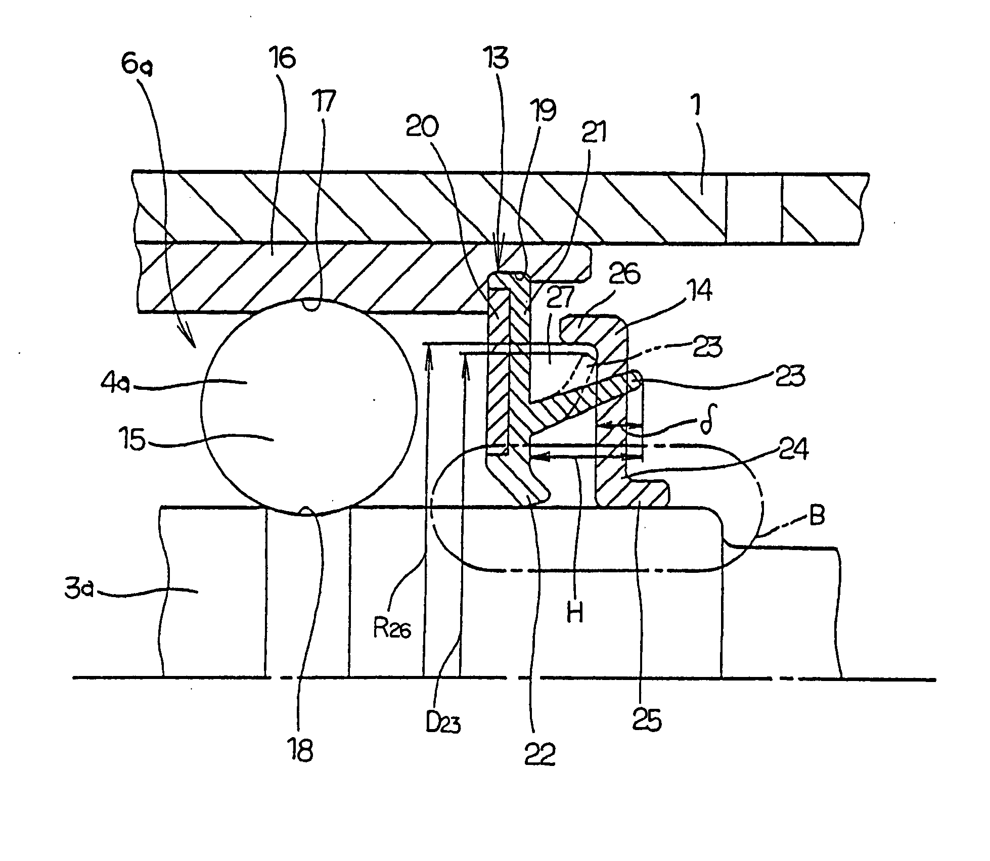
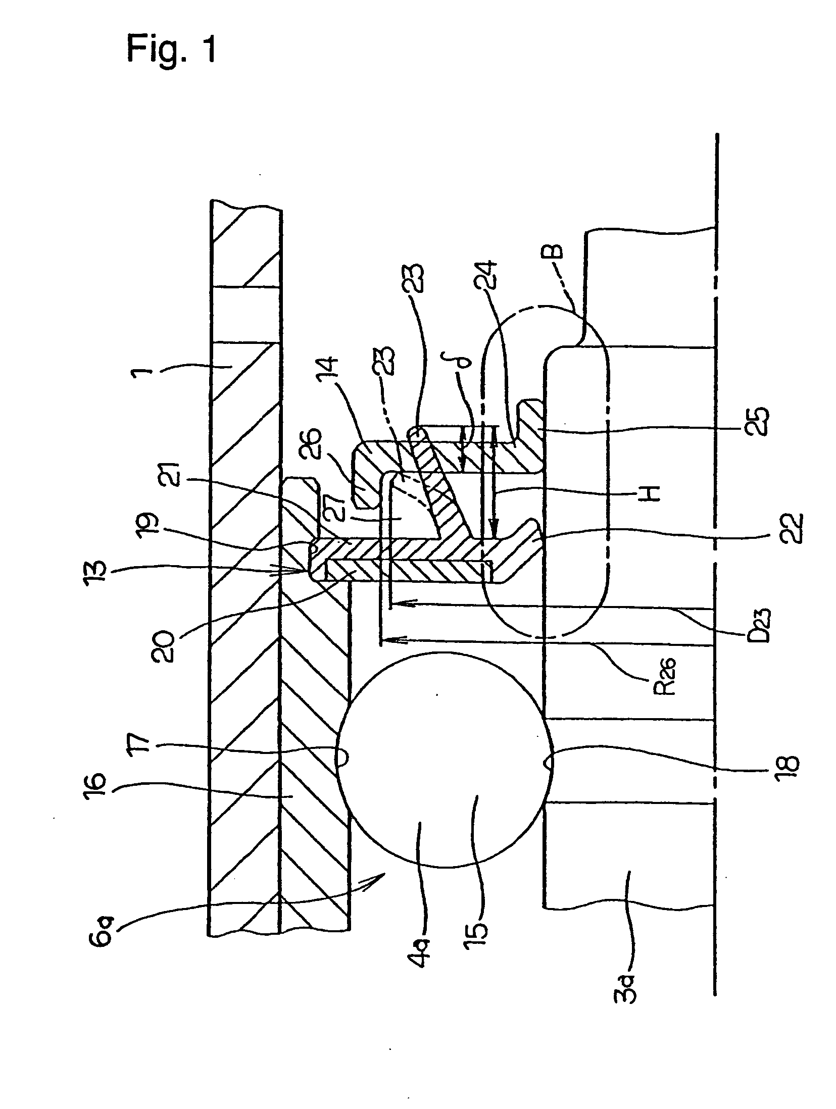
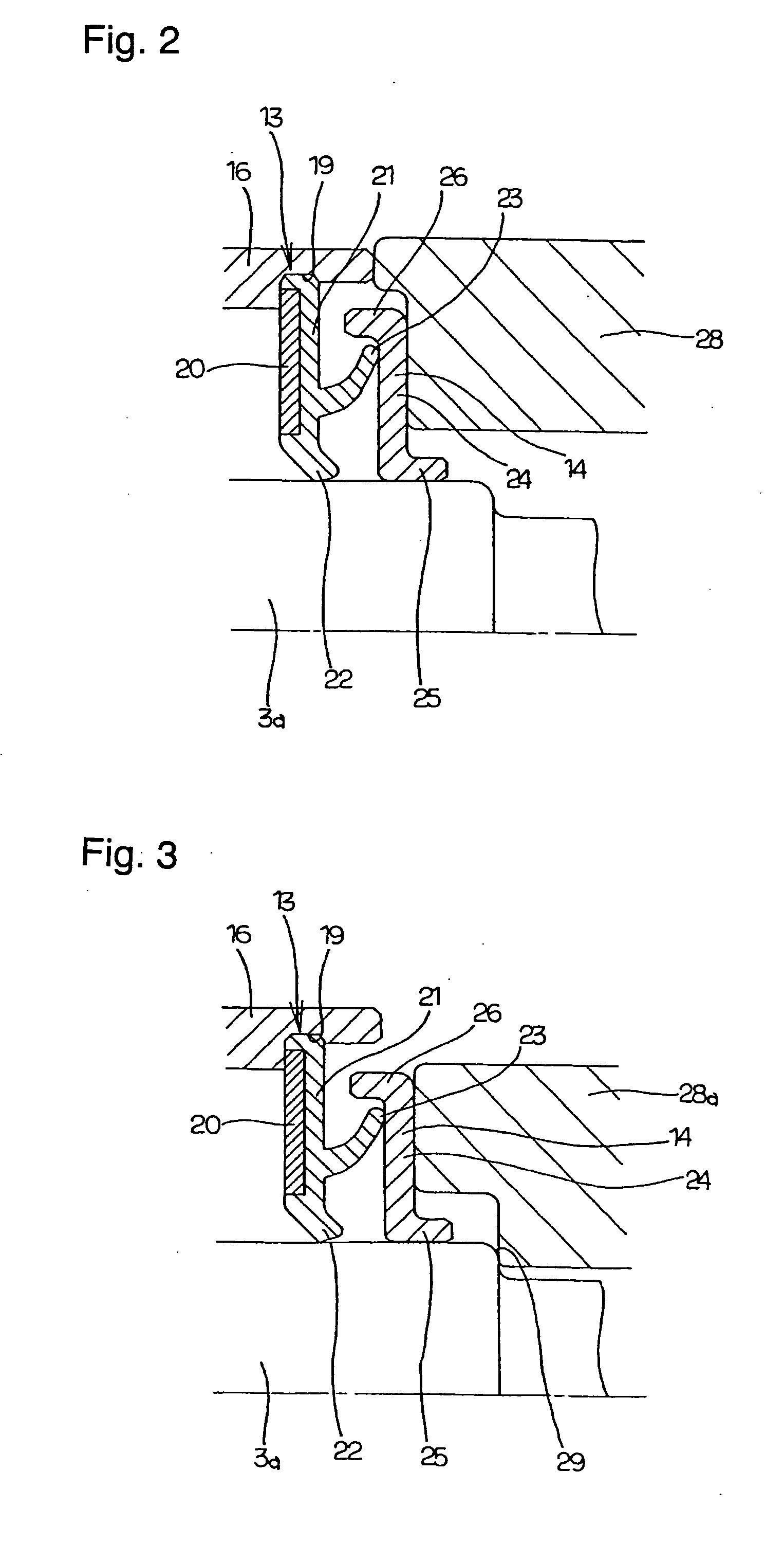
[0033] Referring to FIG. 1, the first example of the construction of a seal apparatus for a water pump to which the method of assembly of the present invention is applied is explained. The characteristics of the seal apparatus for a water pump to which the method of assembly of this example is applied are that, by suitable regulation of the shape and dimensions of the seal ring 13 and slinger 14 provided in the middle section of the rotating shaft 3a further toward the outside than the mechanical seal 10 (see FIG. 9), it is difficult for steam or hot water passing through the mechanical seal 10 to enter the rolling bearing unit 6a including the plurality of rolling elements (balls) 15. Since the overall construction and the like of the water pump, and the construction and operation of other sections are substantially the same as for a conventional water pump, including the construction shown in FIG. 9, drawings and explanations of identical sections are omitted or simplified, and th...


PUM


Abstract

The tip edge of a second seal lip of an elastic member constituting a seal ring is in sliding contact with a side surface of a slinger. When the slinger is fitted onto and fixed to the rotating shaft, the slinger is pressed by a pressing jig. The shape and dimension of the pressing jig are regulated such that when the tip end of the pressing jig is abutted to the end surface of the outer ring, the deformation amount of the second seal lip is made proper. Accordingly, the operation of assembly can be carried out easily in an industrial method while properly regulating the deformation amount of the second seal lip coming into sliding contact with the side surface of the slinger.

Description

TECHNICAL FIELD [0001] A method of assembly for a seal apparatus for a water pump, a rotation support apparatus for a water pump, and a water pump according to the present invention relates to an improvement of a method of assembly for a seal apparatus for a water pump that is used for circulating coolant water for an automobile engine. BACKGROUND ART [0002] A water pump used for circulating coolant water for an automobile engine is disclosed for example in Japanese Patent Publication No. Tokukai Hei 8-254213, and is constructed as shown in FIG. 9. A cylindrical housing 1 has a mounting flange 2 formed around its outer peripheral surface on the inside end (the inside with reference to the axial direction is the side nearest the engine, and is the right side in all of the figures) which is used for fastening to the cylinder block of the engine. A rolling bearing unit 6 comprising a ball bearing 4 on the inside and a roller bearing 5 on the outside (the outside with reference to the a...

Claims


Application Information

Patent Timeline
IPC IPC(8): F04D29/04F04D29/049F16C33/78F16J15/32
CPCF04D29/049F16J15/3264F16C33/7859F16C19/49F01P5/10F04D29/126F16C33/78F04D29/007F04D29/605F05D2210/11F05D2240/55Y10S415/00Y10S417/00
Inventor IKETANI, MASAMICHI
Owner NSK LTD
Learn More