
Bypassing pixel clock generation and CRTC circuits in a graphics controller chip

Active Publication Date: 2005-03-24
GENESIS MICROCHIP
View PDF99 Cites 73 Cited by
  • Summary
  • Abstract
  • Description
  • Claims
  • Application Information

AI Technical Summary

Problems solved by technology

Therefore, even in those situations where a pixel clock rate is not meaningful (such as with fixed pixel displays, such as LCDs), conventional video processors require that a CRT controller unit force a video signal that will not be displayed on a CRT type display to conform to legacy CRT requirements.

Method used


Image

  • Bypassing pixel clock generation and CRTC circuits in a graphics controller chip
  • Bypassing pixel clock generation and CRTC circuits in a graphics controller chip
  • Bypassing pixel clock generation and CRTC circuits in a graphics controller chip

Examples


Embodiment Construction

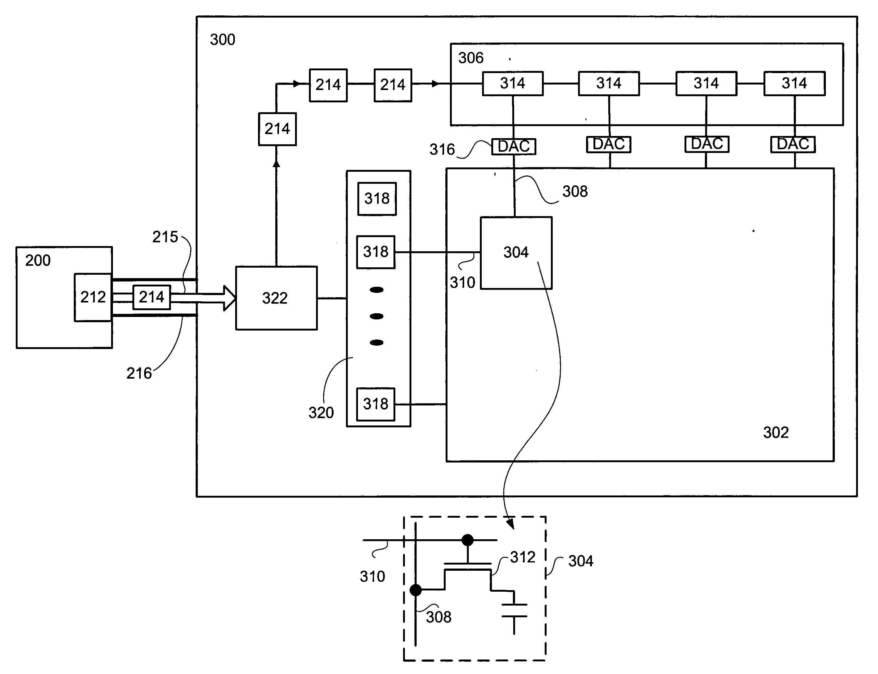
[0019] Reference will now be made in detail to a particular embodiment of the invention an example of which is illustrated in the accompanying drawings. While the invention will be described in conjunction with the particular embodiment, it will be understood that it is not intended to limit the invention to the described embodiment. To the contrary, it is intended to cover alternatives, modifications, and equivalents as may be included within the spirit and scope of the invention as defined by the appended claims.

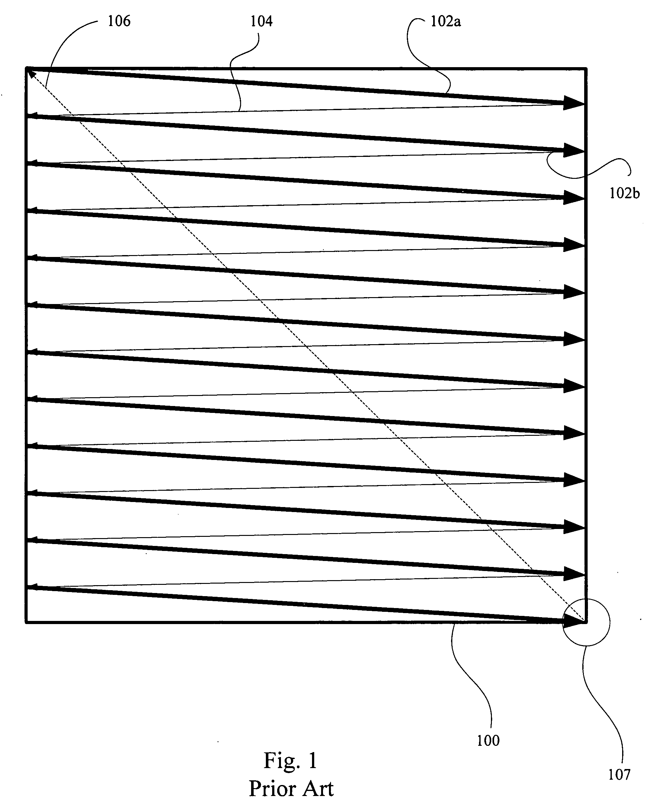
[0020] Until most recently, almost all TVs in use today rely on a device known as the cathode ray tube, or CRT, to display their images. In order to display an image on the entire screen, electronic circuits inside the TV use magnetic deflection coils (a horizontal deflection coil to move the beam from left to right and a vertical deflection coil to move the beam up and down) to move the electron beam in a “raster scan” pattern across and down the screen. In order to disp...


PUM


Abstract

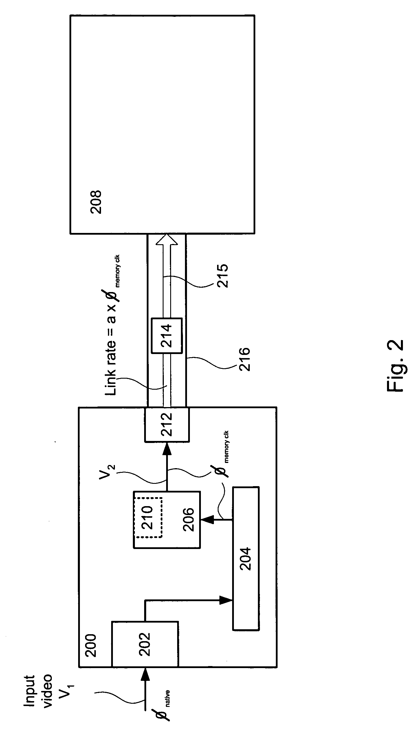
In a video processor unit, a method of providing a video data stream at a clock rate that is independent of a pixel clock rate. Receiving native video data from a video source at a native clock rate, storing the video data in a memory unit, reading selected portions of the video data at a memory clock rate, rasterizing the selected video data, packetizing the rasterized video data, sending the packetized video data to a display unit by way of a link at a link rate, wherein the link rate is directly related to the memory clock rate.

Description

CROSS REFERENCE TO RELATED APPLICATIONS [0001] This patent application takes priority under 35 U.S.C. 119(e) to (i) U.S. Provisional Patent Application No. 60 / 504,060 (Attorney Docket No. GENSP013P2) filed on Sep. 18, 2003, entitled “DIGITAL / ANALOG VIDEO INTERCONNECT AND METHODS OF USE THEREOF” by Kobayashi, and (ii) U.S. Provisional Patent Application No. 60 / 562,737 (Attorney Docket No. GENSP 113P) filed on Apr. 15, 2004, entitled “BYPASSING PIXEL CLOCK GENEARATION AND CRTC CIRCUITS IN A GRAPHICS CONTROLLER CHIP”by Kobayashi each of which are hereby incorporated by reference herein in their entirety. This application is also related to the following co-pending U.S. Patent applications each of which are incorporated by reference, (i) U.S. patent application Ser. No. 10 / 726,802 (Attorney Docket No.: GENSP014), entitled “METHOD OF ADAPTIVELY CONNECTING A VIDEO SOURCE AND A VIDEO DISPLAY” naming Kobayashi as inventor; (ii) U.S. patent application Ser. No. 10 / 726,438 (Attorney Docket No...

Claims


Application Information

Patent Timeline
IPC IPC(8): G06F3/14G09G3/20G09G3/36G09G5/00G09G5/06G09G5/395H04N5/00H04N5/44H04N5/66H04N7/12H04N7/173H04N21/431
CPCG06F3/14G09G3/3611G09G5/006G09G2370/04G09G5/395G09G2310/027G09G2330/021G09G5/06H04N7/12
Inventor KOBAYASHI, OSAMU
Owner GENESIS MICROCHIP
Learn More