Oil tight type chain tensioner

a chain tensioner and oil tight technology, applied in the direction of gearing details, belts/chains/gearrings, gearing details, etc., can solve the problems of increasing the load of the engine driving the oil pump, affecting the movement of the rod, and the oil in the housing affecting the rod movement, etc., to achieve the effect of suppressing non-uniform wear of the oil seal

Inactive Publication Date: 2005-03-24
TOYOTA JIDOSHA KK +1
View PDF13 Cites 8 Cited by
  • Summary
  • Abstract
  • Description
  • Claims
  • Application Information

AI Technical Summary

Benefits of technology

[0010] Accordingly, it is an objective of the present invention to provide an improved oil tight type chain tensioner that is capable of preferably suppressing non-uniform wear of an oil seal.

Problems solved by technology

However, the oil in the housing restricts the movement of the rod, such that the rod is slowly retracted into the housing.
If the rod is urged to be retracted into the housing by the vibration of the chain, the oil in the housing hampers the movement of the rod.
Since the oil feeding passage has a complex configuration, the passage is relatively complicated to form.
Further, since the oil pump must feed the tensioner, the oil discharge amount of the oil pump becomes relatively large, thus increasing the load of the engine driving the oil pump.
This makes it difficult to save fuel consumption of the engine.
If the aforementioned tension is increased, the friction between the oil seal and the rod is also increased, thus promoting wear of the oil seal.
Since the tension acts non-uniformly in a circumferential direction of the rod due to inclination or radial displacement of the rod, the wearing amount of the oil seal becomes non-uniform in the circumferential direction of the rod.
As a result, focal and excessive wear may occur at a circumferential section of the oil seal.
However, though the problem regarding the non-uniform wear of the oil seal is solved by the diaphragm, the diaphragm may be deteriorated due to the heat in the chain case.
If the diaphragm is damaged due to the thermal deterioration, the oil in the housing may enter the air chamber, hampering the operation of the tensioner including pressing of the chain and suppressing of the chain vibration.

Method used


Image

  • Oil tight type chain tensioner
  • Oil tight type chain tensioner
  • Oil tight type chain tensioner

Examples


Embodiment Construction

[0025] An embodiment of the present invention will hereafter be described with reference to FIGS. 1 to 3.

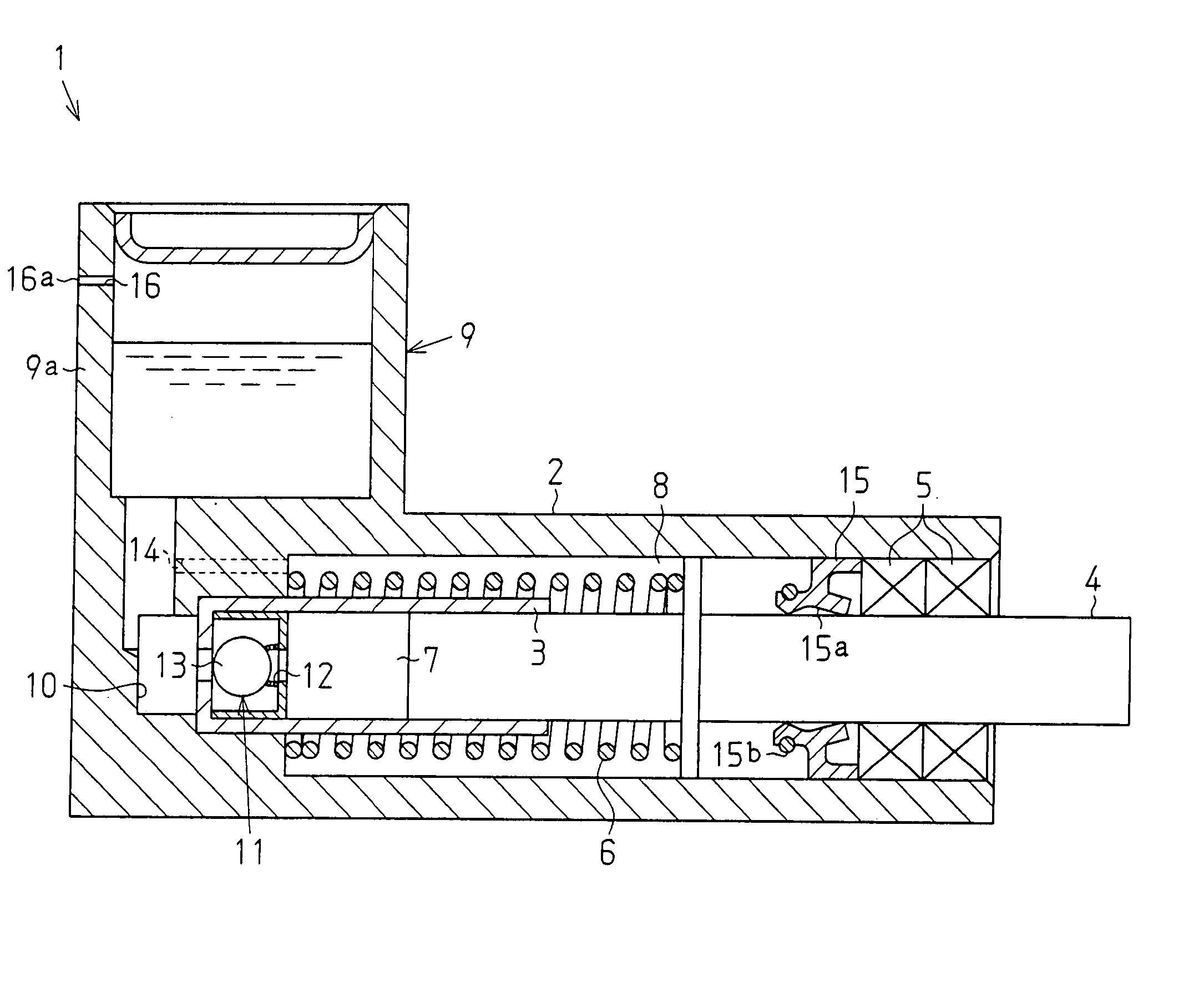
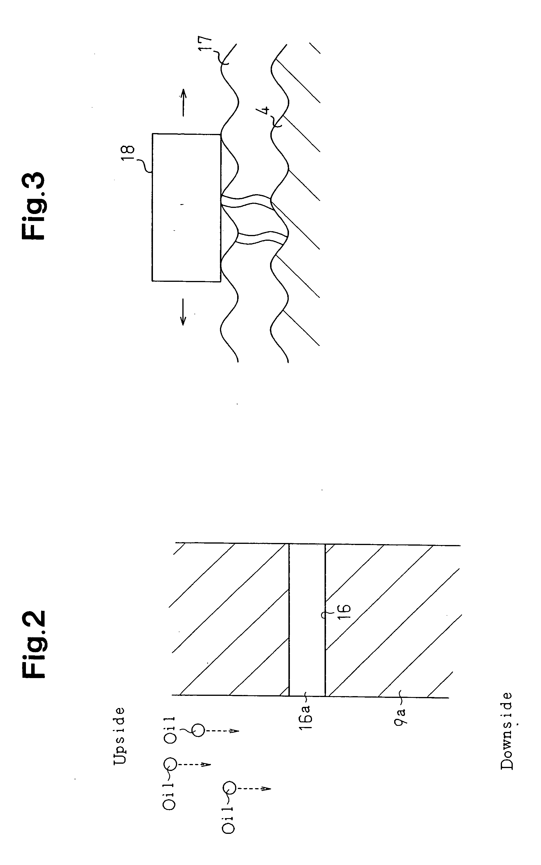
[0026]FIG. 1 is a cross-sectional view showing the interior structure of an oil tight type chain tensioner 1 according to the embodiment of the present invention. The tensioner 1 is employed for a chain transmitting rotation of an engine crankshaft to a camshaft. The tensioner 1 is accommodated in a chain case receiving the chain. Engine oil is supplied to the interior of the chain case for lubricating the chain. When revolving in the chain case, the chain splashes the engine oil, which is relatively hot, exposing the interior of the chain case to the heat of the engine oil.

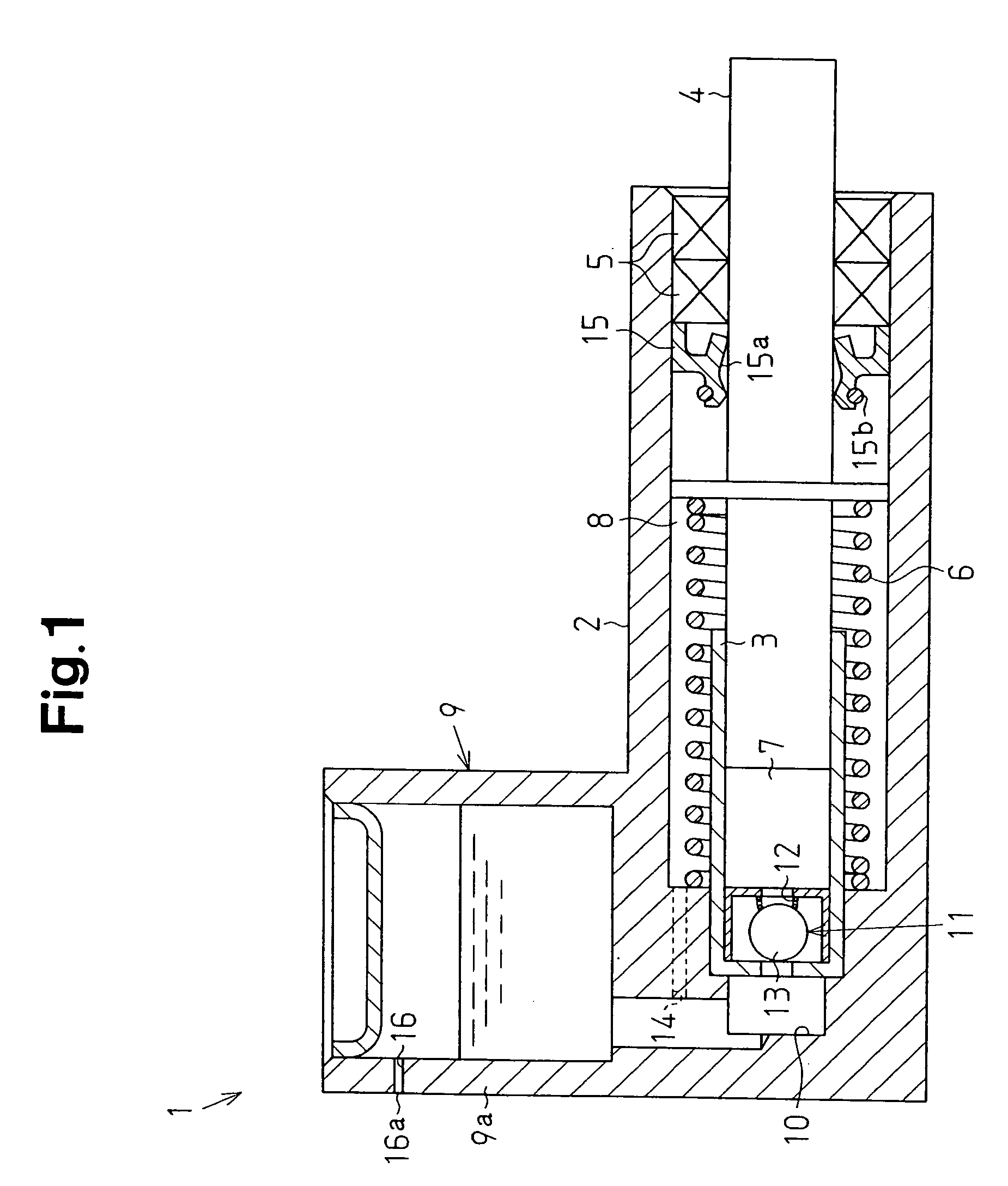
[0027] The tensioner 1 includes a housing 2 in which a cylinder 3 is accommodated. A rod 4 is received in the cylinder 3 such that the rod 4 is reciprocally movable. A pair of annular rod guides 5 are deployed between the inner circumferential surface of the housing 2 and the outer circumferential surface of...


PUM


Abstract

An oil tight type chain tensioner applies tension to a chain used in an engine. The tensioner includes a housing, in which oil is sealed, and a reciprocating rod extending from the interior of the housing to the exterior for pressing the chain. An oil seal is located between the outer circumferential surface of the rod and the inner circumferential surface of the housing. A reservoir for retaining the oil is communicated with the interior of the housing. This structure permits the oil to flow between the interior of the housing and the reservoir in correspondence with the reciprocation of the rod. The reservoir has a hole for permitting air communication from the interior of the reservoir to the exterior but restricting an oil flow from the exterior of the reservoir to the interior.

Description

BACKGROUND OF THE INVENTION [0001] The present invention relates to oil tight type chain tensioners. [0002] In an engine including a chain for transmitting rotation of a crankshaft to a camshaft, a tensioner is deployed for pressing the chain in order to apply a certain level of tension to the chain. The tensioner includes a housing retaining oil and accommodating a rod. The rod is projected from the housing by urging force of a spring, thus pressing the chain. If the chain vibrates in this state, the rod may be urged to be retracted into the housing. However, the oil in the housing restricts the movement of the rod, such that the rod is slowly retracted into the housing. This suppresses the vibration of the rod. [0003] Conventionally, an oil fed type tensioner is employed for the aforementioned purpose. In this type of tensioner, an oil pump driven by the engine supplies oil to the interior of the housing of the tensioner. Meanwhile, the oil is allowed to leak from the housing, thu...

Claims


Application Information

Patent Timeline
Patent Type & Authority Applications(United States)
IPC IPC(8): F16H7/06F16H7/08F16H57/027F16H57/035
CPCF16H7/0836F16H2007/0859F16H2007/0806
Inventor TOMITA, YUKIHARUKANO, TOMOHIRONAKAKUBO, KATSUYAYOSHIMURA, TOMONORIHASHIMOTO, HIROSHIOHARA, HITOSHI
Owner TOYOTA JIDOSHA KK
Why Eureka
Try Eureka