Osseous achoring device for a prosthesis

a prosthesis and osseous achoring technology, applied in the field of osseous achoring devices, can solve the problem of limited length of impacting pins, and achieve the effect of improving the stability and stability of the osseous achoring pins

Inactive Publication Date: 2005-03-24
LDR MEDICAL
View PDF7 Cites 108 Cited by
  • Summary
  • Abstract
  • Description
  • Claims
  • Application Information

AI Technical Summary

Benefits of technology

[0007] The aim of the present invention is thus to overcome the disadvantages of prior art by means of an osseous anchoring device that makes it

Problems solved by technology

The length of these impacting pins is nonetheless limited by the fact that the two vertebrae must b

Method used


Image

  • Osseous achoring device for a prosthesis
  • Osseous achoring device for a prosthesis
  • Osseous achoring device for a prosthesis

Examples


Embodiment Construction

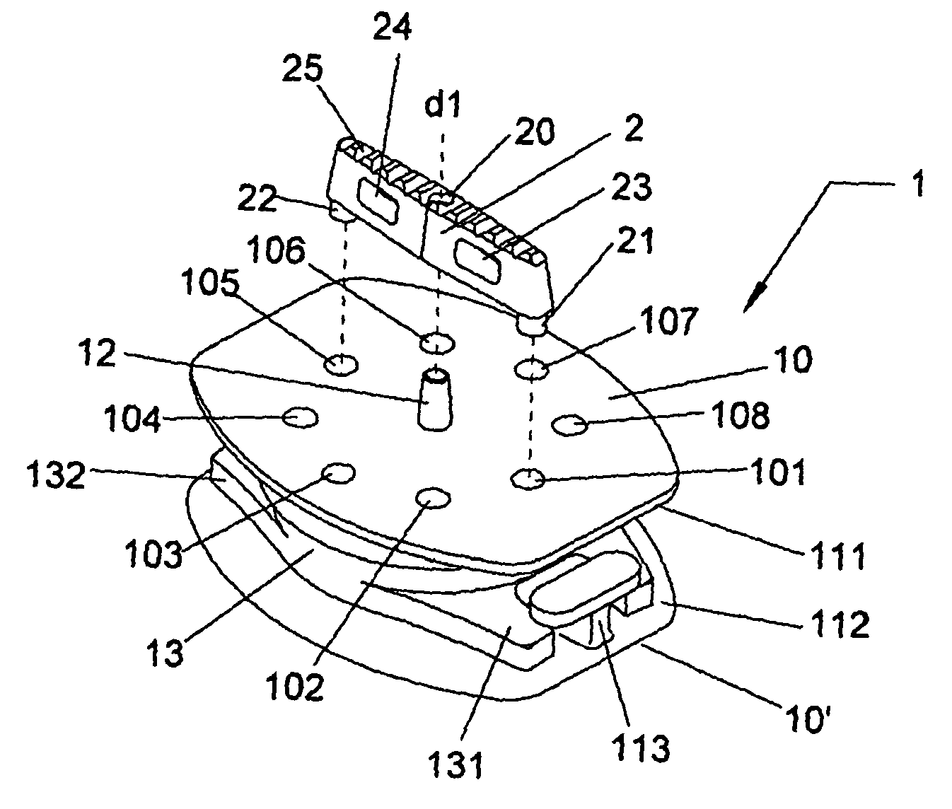
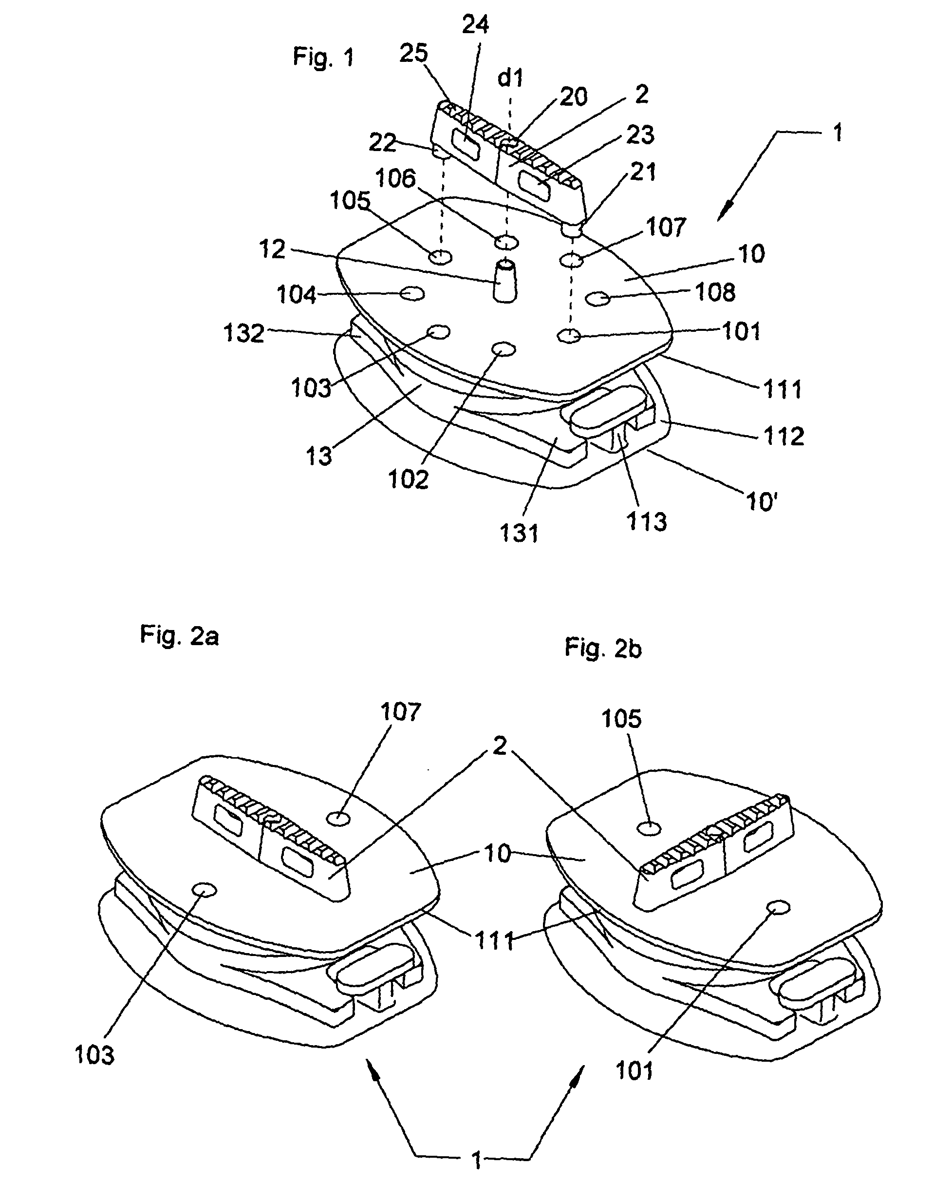
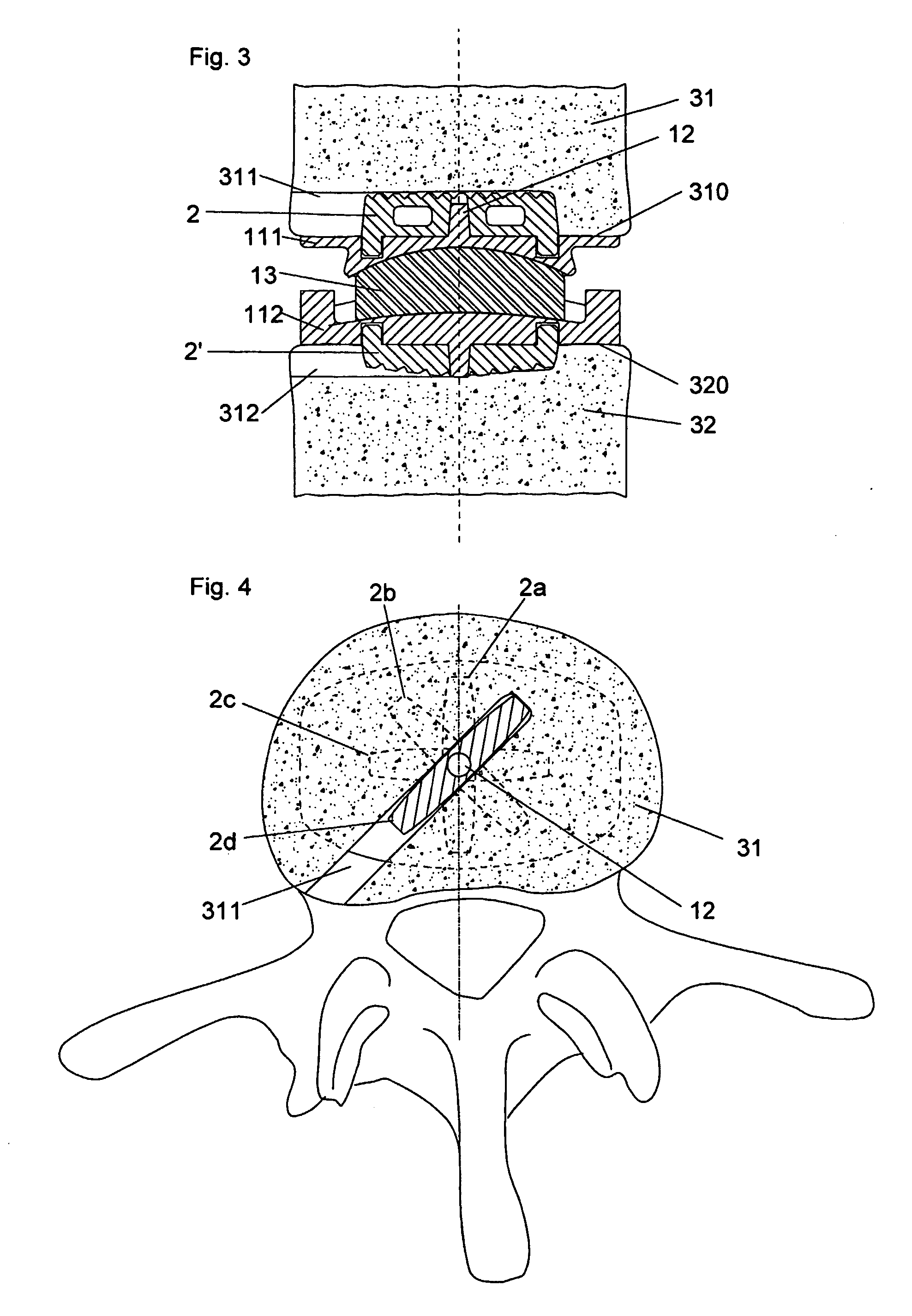
[0024] The present description refers to an anchoring device according to the invention applied to an inter-vertebral disc prosthesis of a functional type, meaning that it allows relative movement of the two vertebrae.

[0025] Although the invention is described here for the case of such a prosthesis, it must be evident that the anchoring device according to the invention can also be applied to other types of devices, for example nonfunctional such as, for example, an arthrodesic thoracic cage or a tumorous cage. In the present description, the term “prosthesis” must therefore be understood as being able to be applied equally well to a prosthesis as to an implant.

[0026] The anchoring device according to the invention can also be used for maintaining other types of prostheses, used for other reasons and in other regions of the body, when they comprise a part bearing against an osseous surface. The device according to the invention can also be combined with other anchoring devices, su...


PUM


Abstract

The present invention relates to an osseous anchoring device intended to maintain a prosthesis or an implant in position, and in particular an anchoring device for an intervertebral prosthesis. The anchoring device for a prosthesis (1), or an implant, is intended to be anchored in a prepared osseous surface (310, 321). It comprises at least one protruding element extending beyond the prosthesis, this protruding element being able to be positioned relative to the prosthesis in a plurality of positions thus making it possible to choose a position adapted to the case to be treated or to the chosen mode of inserting the prosthesis or the anchoring device.

Description

FIELD OF INVENTION [0001] The present invention relates to an osseous anchoring device intended to maintain a prosthesis or implant in position, and in particular an intervertebral prosthesis. BACKGROUND OF THE INVENTION [0002] When an internal prosthesis bears on an osseous body or is inserted between several osseous bodies, the position of this prosthesis is often maintained in place by reliefs or irregularities of protruding form on one face of this prosthesis and acting as anchor in the surface of this osseous body. [0003] In the case of intervertebral prostheses, in particular functionally replacing an intervertebral disc, this maintenance can be ensured in several ways. One possibility consists of providing pins extending beyond the surface of the prosthesis, these pins being encrusted, or impacted, in the surface of the vertebral disc, under the effect of the pressure exerted by the vertebrae surrounding the prosthesis. [0004] The length of these impacting pins is nonetheless...

Claims


Application Information

Patent Timeline
IPC IPC(8): A61F2/44A61FA61F2/00A61F2/28A61F2/30A61F2/46
CPCA61F2/28A61F2250/0062A61F2/4425A61F2002/30327A61F2002/30332A61F2002/30365A61F2002/30372A61F2002/30538A61F2002/3054A61F2002/30604A61F2002/30607A61F2002/30649A61F2002/30662A61F2002/30884A61F2002/30899A61F2002/30904A61F2002/443A61F2220/0033A61F2250/0006A61F2250/0039A61F2/30771
Inventor HUPPERT, JEANAMEIL, MARC
Owner LDR MEDICAL
Why Eureka
Try Eureka