
Multi-mode in-vehicle control unit with network selectivity for transmitting vehicle data for fleet management

a technology of vehicle data and network selectivity, applied in the field of systems, can solve the problems of inability to fully service the cost of satellite and cellular telephone systems to transmit status information collected by vehicles in the fleet of companies, and the general economic inability to meet the needs of large companies' status information transmission, etc. cost-effective, cost-effective

Inactive Publication Date: 2005-03-24
META PLATFORMS INC
View PDF29 Cites 116 Cited by
  • Summary
  • Abstract
  • Description
  • Claims
  • Application Information

AI Technical Summary

Benefits of technology

[0012] Vehicle data to be sent over the cellular telephone network can also be stored for later transmission so that it can be sent in a batch mode. This allows the vehicle data to be sent at a time when the cost to use a transmission network is less expensive. For example, cellular telephone network air costs are reduced at night. Consequently, if vehicle data must be sent using the cellular telephone network, preferably it is stored, and later transmitted in an overnight batch transmission. Since cellular telephone network charges are reduced at night, transmitting the vehicle data overnight in a batch transmission can be cost effective.

Problems solved by technology

However, conventional wireless data systems are generally limited in terms of their coverage area and capacity.
Often, therefore, wireless data systems cannot fully service large companies' status information transmission needs.
However, the costs associated with satellite and cellular telephone systems to transmit status information collected by vehicles in a companies' vehicle fleet is generally economically unfeasible.
Such charges generally are uneconomical due to the high cost of cellular air time.

Method used


Image

  • Multi-mode in-vehicle control unit with network selectivity for transmitting vehicle data for fleet management
  • Multi-mode in-vehicle control unit with network selectivity for transmitting vehicle data for fleet management
  • Multi-mode in-vehicle control unit with network selectivity for transmitting vehicle data for fleet management

Examples


Embodiment Construction

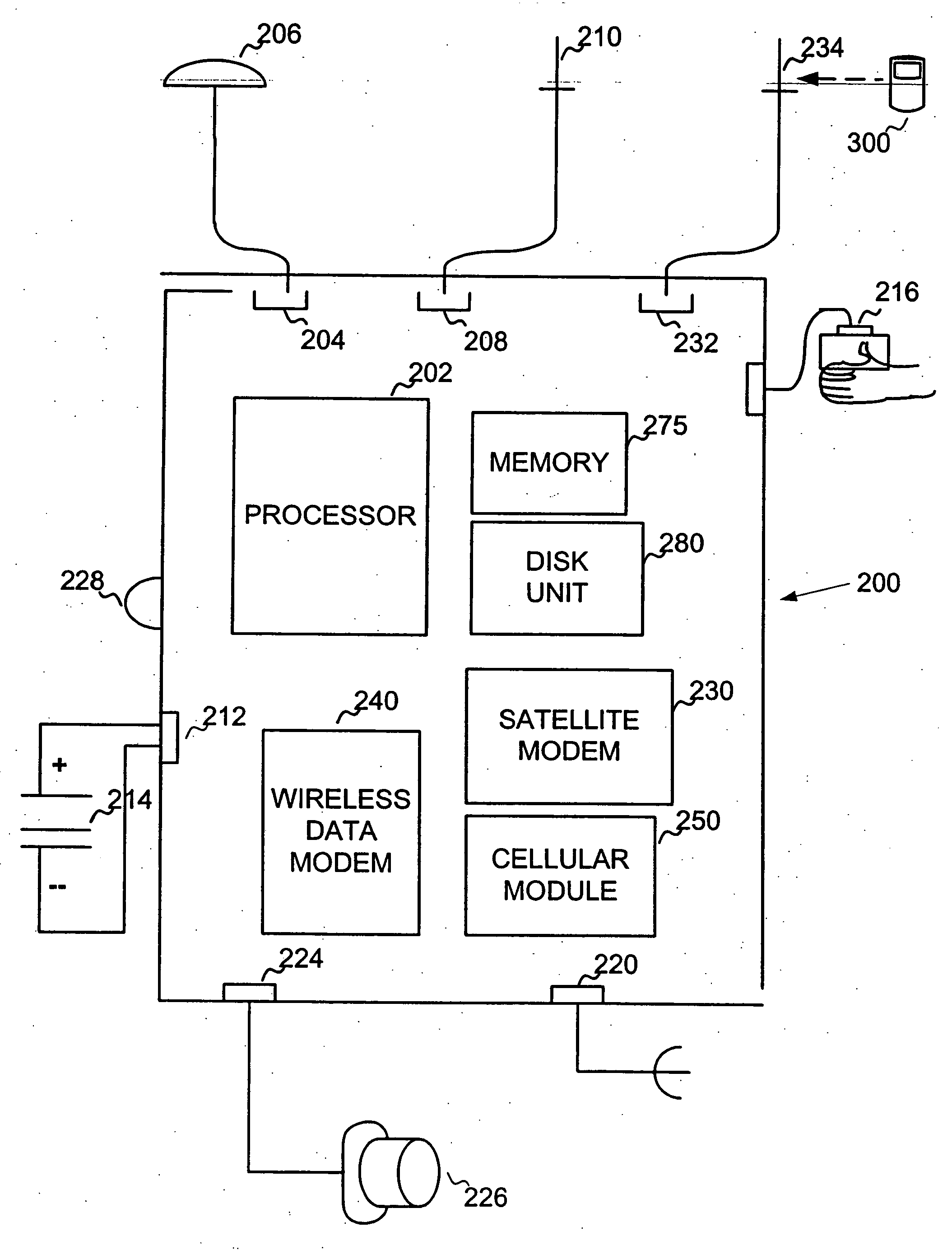
[0020] The present invention is directed to a system and method for transmitting vehicle data for any or all of the vehicles in a fleet of vehicles to a processing center. The vehicle data can be data related to the status of the vehicle, including for example, vehicle speed, vehicle location, time a vehicle spends at a location, time vehicle is moving, time of ignition and other vehicle status data. The vehicle data can also be data related to an emergency. For example, the vehicle data can be an indication or notification that a user has pressed an emergency alert button as described in the '368 application.

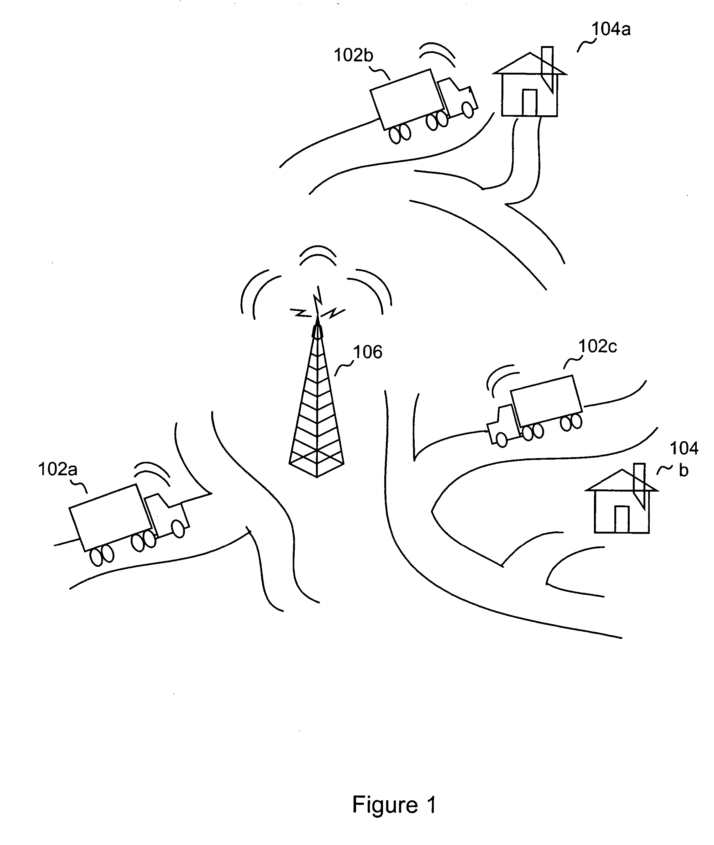
[0021] As described above, a variety of companies rely on fleets of vehicles in their normal operations. FIG. 1 is a schematic diagram illustrating an exemplary environment for implementing the present invention. Vehicles 102a, 102b and 102c are vehicles in a company's fleet. Vehicle 102b is stationary and located a customer 104a's location. Vehicle 102c has been dispatched to...


PUM


Abstract

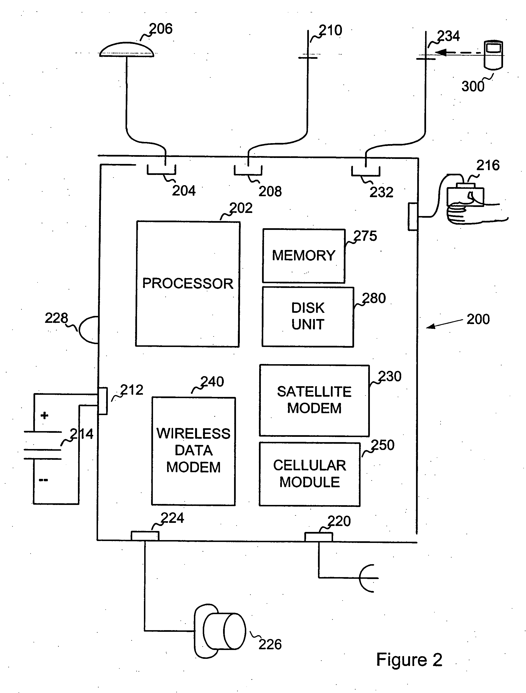
A multi-mode in-vehicle control unit (ICU) contains a plurality of modems. Each modem allows the multi-mode ICU to transmit vehicle data over a different kind of transmission network. Exemplary transmission networks include wireless data networks, cellular telephone networks and satellite networks. Vehicle data is collected. The multi-mode ICU selects one of the modems for transmission of vehicle data to a processing center. Priorities can be assigned to the transmission networks and or modems to control order the transmission network selection process.

Description

CROSS REFERENCE TO RELATED APPLICATIONS [0001] This application is a continuation of U.S. application Ser. No. 09 / 988,304 filed Nov. 19, 2001, which in turn is a continuation-in-part of U.S. application Ser. No. 09 / 474,368 filed Dec. 29, 1999, (the “'368 application”), now U.S. Pat. No. 6,356,841, which is hereby incorporated by reference in its entirety.BACKGROUND [0002] 1. Field of the Invention [0003] The present invention relates generally to systems that manage fleets of vehicles. More particularly, the present invention relates to a multi-mode in-vehicle control unit for transmitting vehicle data to a processing center to support fleet management functions. [0004] 2. Background of the Invention [0005] Many companies use a fleet of vehicles to transport personnel, equipment and / or packages to a particular destinations. For example, companies in service industries have a fleet of vehicles to carry service technicians and equipment to customer locations in response to service req...

Claims


Application Information

Patent Timeline
Patent Type & Authority Applications(United States)
IPC IPC(8): G01S5/00G01S5/14G01S19/25G01S19/34G08B25/01
CPCG01S5/0036G01S19/16G08B25/016G07C5/008G01S19/17G06Q10/0833
Inventor TIMKO, JERRY R.HAMRICK, MARVIN R.
Owner META PLATFORMS INC
Learn More