
Method, system and device for predictive error recognition in a plant

a technology of predictive error recognition and manufacturing system, applied in the direction of testing/monitoring control system, instruments, nuclear elements, etc., can solve the problem of expensive supervision of a complex plant environment for predictive error recognition

Active Publication Date: 2005-03-24
SIEMENS AG
View PDF8 Cites 91 Cited by
  • Summary
  • Abstract
  • Description
  • Claims
  • Application Information

AI Technical Summary

Benefits of technology

[0012] Up to now it is very expensive to supervise a complex plant environment entirely for predictive error recognition. Therefore only security relevant and expensive components of a plant are supervis...

Problems solved by technology

Up to now it is very expensive to supervise a complex plant environment entirely for predictive error recognition.

Method used


Image

  • Method, system and device for predictive error recognition in a plant
  • Method, system and device for predictive error recognition in a plant
  • Method, system and device for predictive error recognition in a plant

Examples


Embodiment Construction

[0025] Overview

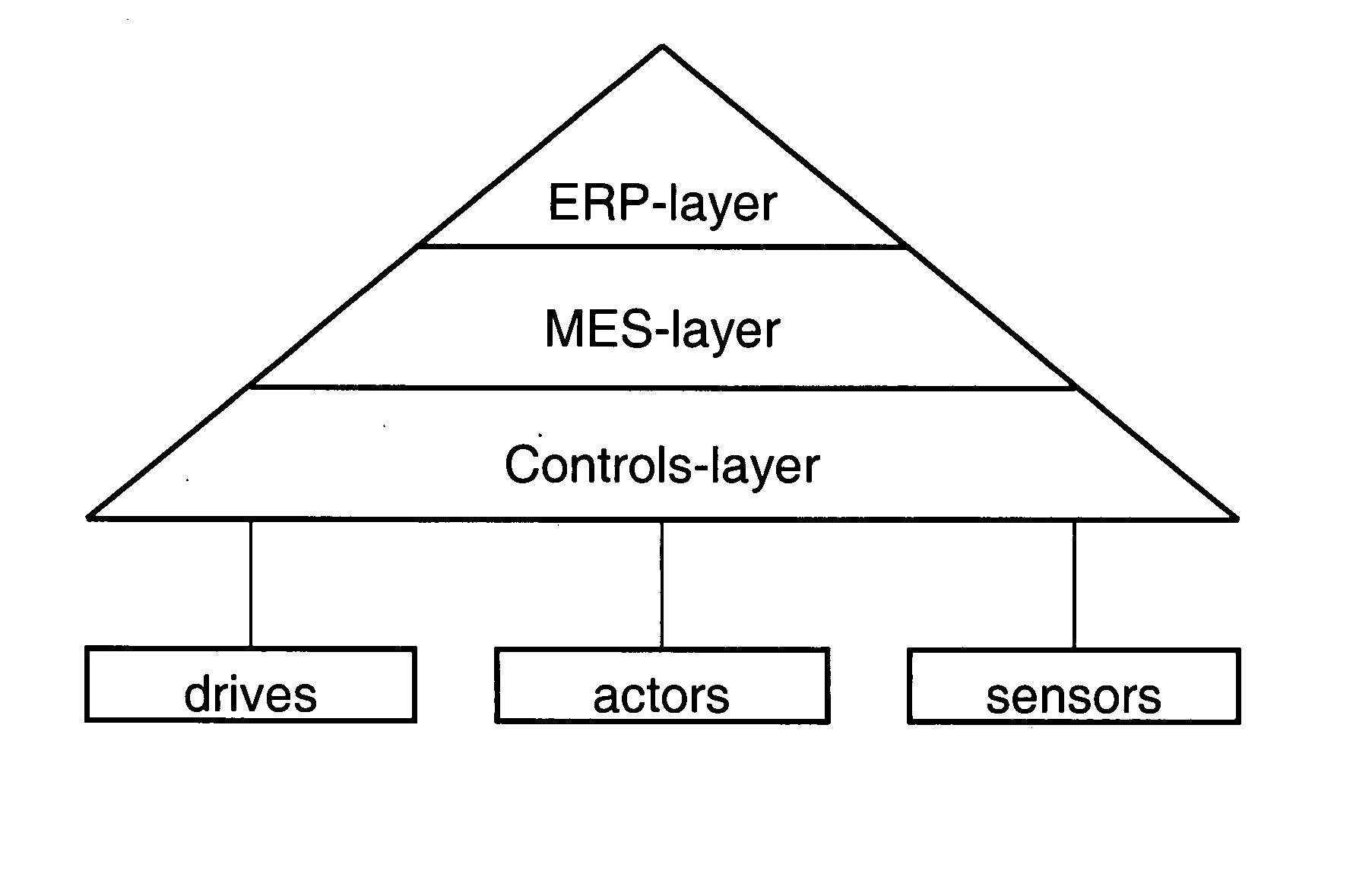
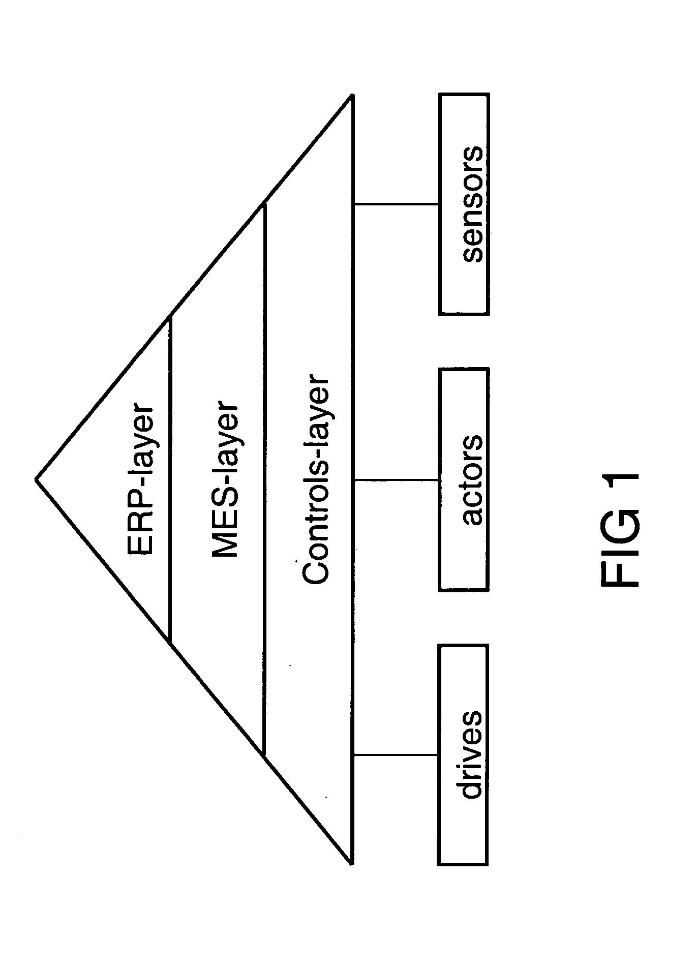
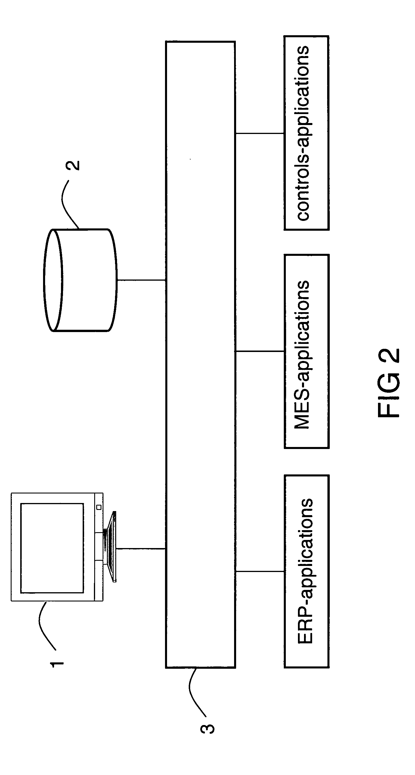
[0026] A concept of the invention involves the continuously collecting of data in a manufacturing system to get a sound base for a predictive recognition of errors. For example this data collection can be accomplished by online capturing and monitoring data coming from automation components or automation applications from all layers of the automation hierarchy (see FIG. 1). Advantageously the monitored data can be densified using statistical methods or data mining mechanisms to focus them and to reduce the amount of data. Structure information regarding the data based on the automation hierarchy or based on the topology of a plant (e.g. the break down in plant / line / cell / station) can also be used to reduce the amount of the monitored data. Furthermore a condensation of the monitored data can be achieved by functional containment to involved components or applications. The monitored data can be stored in a data base 2. This data base can be implemented as a ring puffer...


PUM


Abstract

Method, system and device for predictive recognition of errors in a manufacturing system, said comprising: online monitoring of data of the manufacturing system; and online comparing said data with archived error patterns to predict errors supposed to occur in the manufacturing system; whereby the archived error patterns are built and recognized by statistical methods and data mining methods. The present invention can be used for discrete or continuous or batch processes.

Description

CROSS REFERENCE TO RELATED APPLICATIONS [0001] This application claims the benefits of the provisional U.S. application 60 / 505,699 filed Sep. 24, 2003.FIELD OF THE INVENTION [0002] The present invention relates in general to a method, a system and a device for predictive error recognition, and in particular to a method, a system and a device for predictive error recognition in manufacturing systems, such as plants. BACKGROUND OF THE INVENTION [0003] Production facilities, commonly referred to as plants, continue to increase in complexity due to automation and interconnections between sections of the plant, individual machines within the plant and interconnections between different layers of the “automation pyramid”, among other reasons. Typically the “automation pyramid” is classified into the following layers: the ERP-layer (Enterprise Resource Planning), the MES-layer (Manufacturing Execution System) and the controls-layer. Coping with this increasing complexity is difficult for p...

Claims


Application Information

Patent Timeline
IPC IPC(8): G06F11/00
CPCG05B23/0283G05B23/024
Inventor GROSS, WOLFGANGSCHUDERER, CHRISTIAN
Owner SIEMENS AG
Features
  • Generate Ideas
  • Intellectual Property
  • Life Sciences
  • Materials
  • Tech Scout
  • Unparalleled Data Quality
  • Higher Quality Content
  • 60% Fewer Hallucinations
Learn More