Forming apparatus and method for constructing concrete columns

Inactive Publication Date: 2005-03-31
HUBER DONALD G +1
View PDF22 Cites 36 Cited by
  • Summary
  • Abstract
  • Description
  • Claims
  • Application Information

AI Technical Summary

Benefits of technology

[0014] In their collapsed configuration the forms are easily stored and transported. At a construction site, the forms can be easily assembled. To assemble, the forms are unfolded and positioned in the location where a concrete column is to be constructed. If desired, sections of reinforcing bar can be placed in the forms to provide reinforcement for the concrete columns. Concrete is then poured into the top of the form, and the hydrostatic pressure of the con

Problems solved by technology

While steel and wood forms are adequate for construction of columns, the materials used to make these forms can be costly.
Additionally, constructing column forms from steel or wood is a labor intensive process that requires some degree of skill.
When paper fiber tubes are left in place for an extended period, before concrete is poured into them, they can deteriorate.
Another problem associated with paper fiber tubes is that the tube can soak up some of the water from the wet concrete.
When this occurs,

Method used


Image

  • Forming apparatus and method for constructing concrete columns
  • Forming apparatus and method for constructing concrete columns
  • Forming apparatus and method for constructing concrete columns

Examples


Embodiment Construction

[0022] Turning now to the drawings, the invention will be described in a preferred embodiment by reference to the numerals of the drawings wherein like numbers indicate like parts.

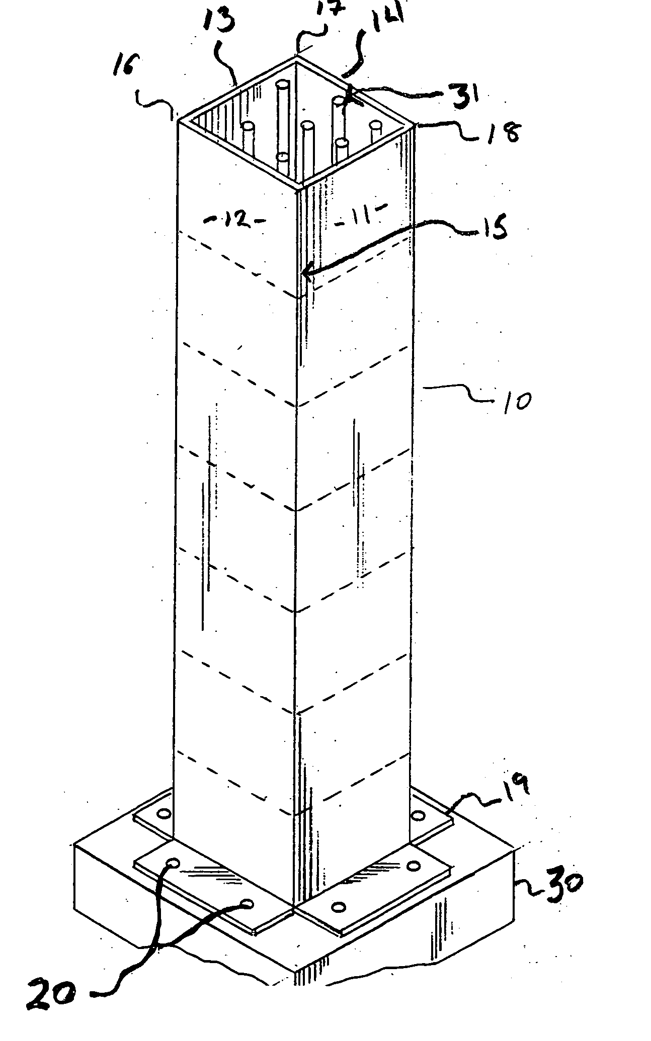
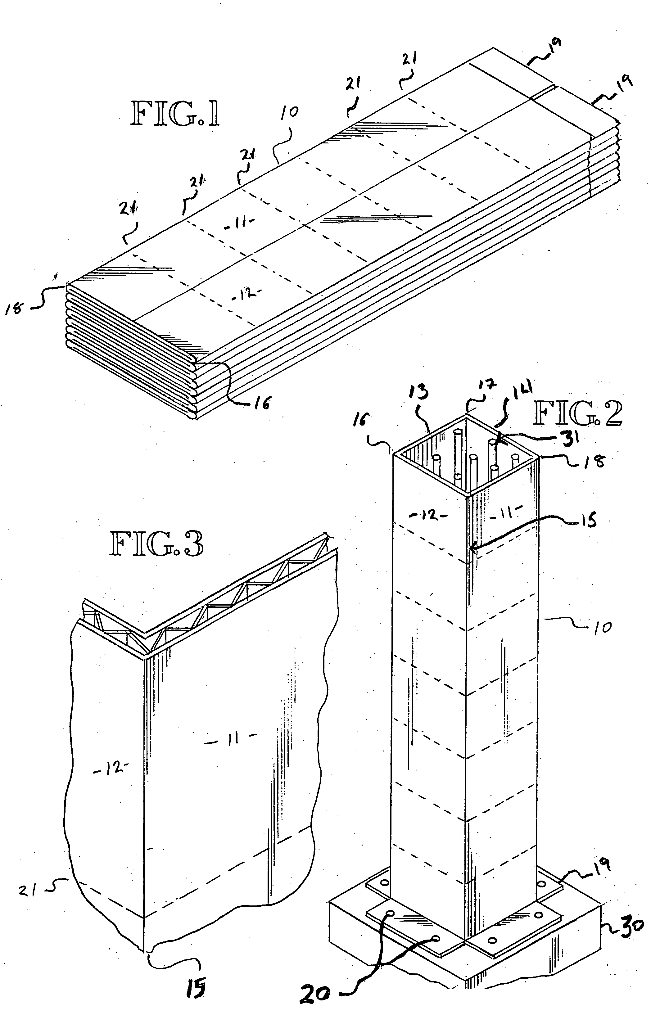
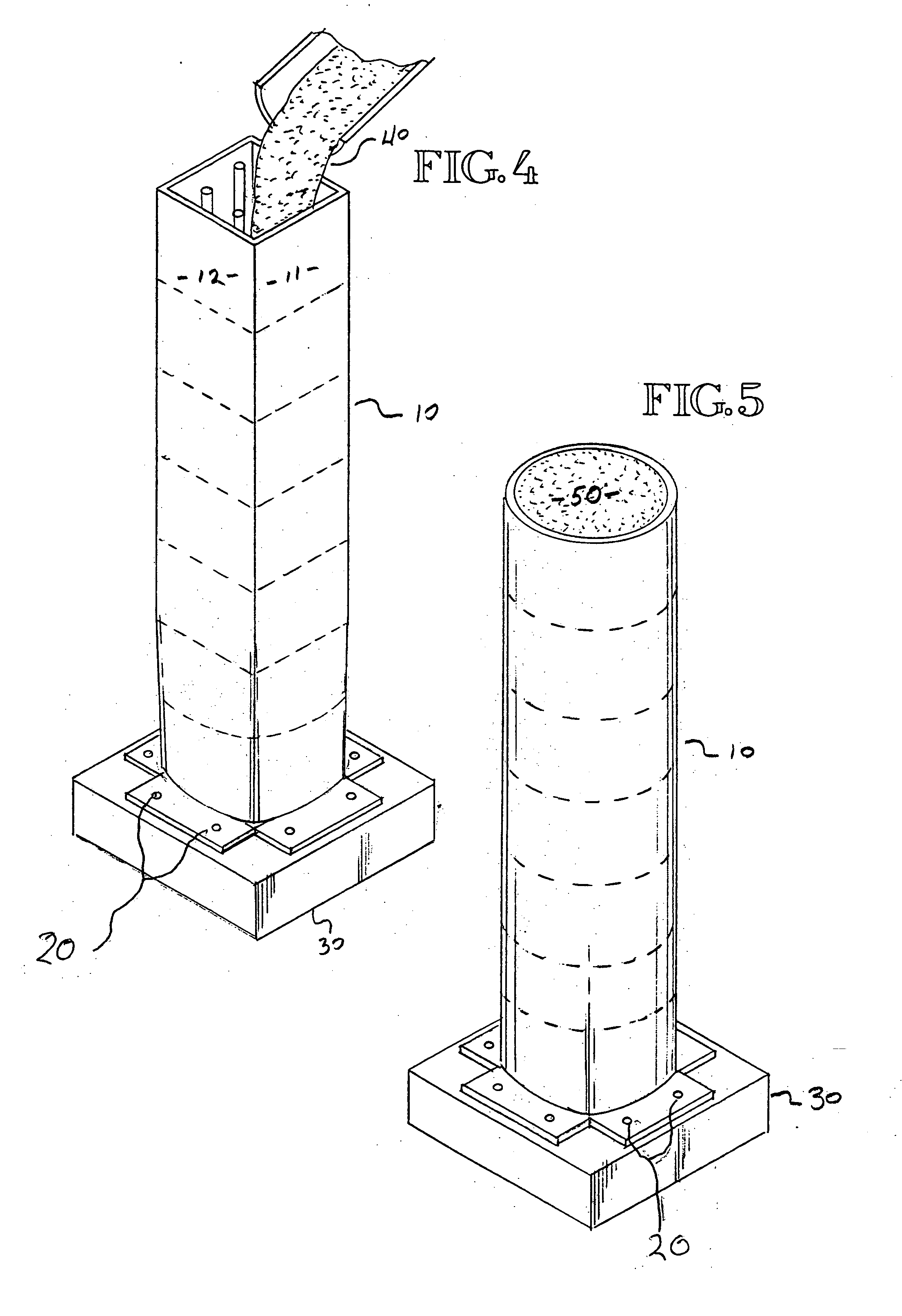
[0023]FIG. 1 shows a preferred embodiment of the pier / column form disclosed herein wherein several forms 10 are folded and stacked for storage or transportation to a construction site. As can be seen in FIG. 2 and FIG. 3, the forms disclosed herein are constructed from corrugated plastic and have four side walls that define an elongated form with an interior for the placement of concrete, and having a generally square cross sectional shape when viewed from above.

[0024] In at least one preferred embodiment, the form is constructed from a single piece of corrugated plastic that has a plurality of seams / folds, which define the corners of the form. The free edges of the sheet of corrugated plastic can be overlapped and connected with an adhesive such as construction glue of the like or other connection means...


PUM

PropertyMeasurementUnit
Lengthaaaaaaaaaa
Electrical resistanceaaaaaaaaaa
Adhesivityaaaaaaaaaa

Abstract

The current invention discloses moisture resistant column forms constructed from corrugated plastic. The forms disclosed herein are lightweight and can be easily assembled at a construction site or remote location. The forms can be positioned over pre-placed sections of reinforcing bars, or sections of reinforcing bars can be placed into a form once it is in position. The forms disclosed in the current invention can be easily removed, but they do not attract insects and therefore do not have to be removed from columns after the concrete has dried. The forms disclosed herein have generally square perimeters when they are assembled and put in place, but after concrete is poured into the form, the side walls will undergo uniform deformation/displacement due to the hydrostatic pressure of the concrete and the resulting column will have a generally circular perimeter. A method of using the forms is also disclosed.

Description

TECHNICAL FIELD [0001] The invention relates to a form that allows piers or columns to be created from poured concrete, for use in building construction. In particular, this invention describes a lightweight and collapsible form for columns. BACKGROUND OF THE INVENTION [0002] Concrete columns are commonly used as upright supports for buildings and other structures. These concrete support structures exist in a wide variety of shapes. Typically, these concrete supports have circular, square or rectangular cross-sections and the size of the support varies depending upon the intended use. [0003] The concrete foundation for a structure anchors the entire structure against settling, slippage and wind lift. It also distributes loads into the ground and protects posts or beams from direct contact with the earth. The foundation may consist of two parts, a footing that distributes the load underground and a pier that raises the bottom of a structure above grade. In some installations the pier...

Claims


Application Information

Patent Timeline
IPC IPC(8): E04G9/05E04G9/08E04G13/02
CPCE04G9/05E04G13/021E04G13/02E04G9/08E04G9/083
Inventor HUBER, DONALD G.HARTMAN, TERRY
Owner HUBER DONALD G
Why Eureka
Try Eureka