
Lifting column for a medical examination table

Inactive Publication Date: 2005-03-31
BREWER COMPANY LLC THE
View PDF99 Cites 11 Cited by
  • Summary
  • Abstract
  • Description
  • Claims
  • Application Information

AI Technical Summary

Benefits of technology

[0004] The present invention provides an adjustable column for an examination table that is compact, efficient, and may be easily serviced if necessary. The column is designed to minimize the space needed for the column while still providing sufficient, sturdy support for a patient resting upon the examination table. Also, the column is designed so that the column height is adaptable over a wider range of heights than possible with the prior art. Likewise, the minimum height of the column is less than previous minimum heights attainable by similar examination tables of the prior art.
[0008] The sleeve sections of the column move relative to one another by guide rails and cam followers located on opposing sides of the column sleeve sections. The guide rails are longitudinally extending with a pair of oppositely disposed parallel guide surfaces. The guide rails are located between the first and second sleeve sections, and the second and third sleeve sections, with accompanying cam followers for each rail. The rails are mounted on the outside and inside of the second sleeve section, and the cam followers have an eccentric diameter for adjustment against the rails. The cam followers are oppositely disposed and spaced apart and are in guiding contact with an oppositely respective disposed parallel guide surface of the guide rail. The design allows for smooth upward and downward movement of the column as well as support for heavier patients without diminishing the effectiveness of the column.
[0009] The design of the column allows easy access for maintenance, as well. Because the rail and cam followers inside the columns may be easily accessed through the top of the column without complicated disassembly of the column, a person may service the column in a quick and efficient manner.

Problems solved by technology

Though these designs assist an examiner in repositioning a patient for different procedures, they do not allow for vertical mobility of the table.
Also, though compact, the base does not provide for the easiest access to all of the parts, if such parts require servicing.

Method used


Image

  • Lifting column for a medical examination table
  • Lifting column for a medical examination table
  • Lifting column for a medical examination table

Examples


Embodiment Construction

[0021] Although the disclosure hereof is detailed and exact to enable those skilled in the art to practice the invention, the physical embodiments herein disclosed merely exemplify the invention which may be embodied in other specific structure. While the preferred embodiment has been described, the details may be changed without departing from the invention, which is defined by the claims.

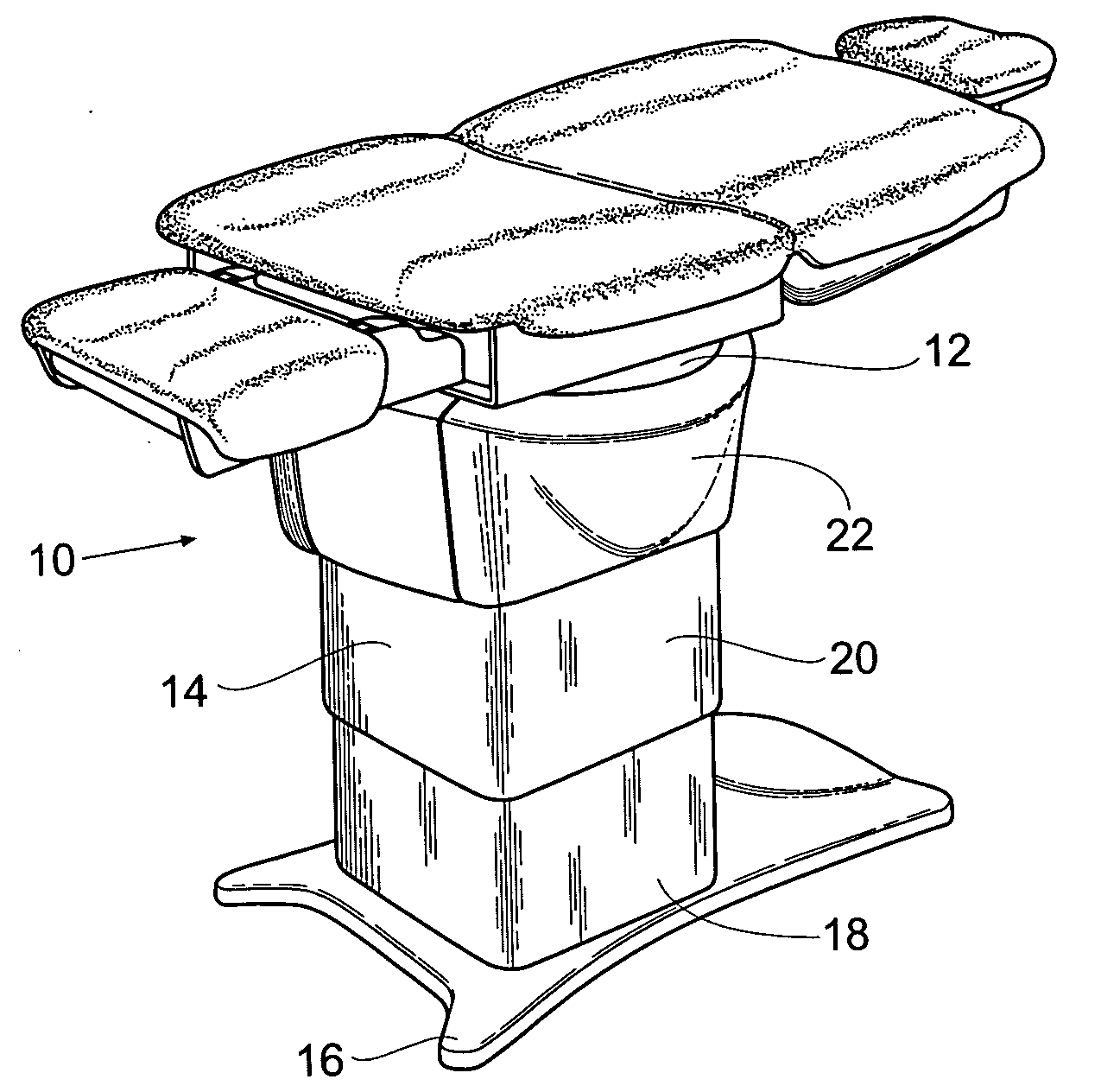
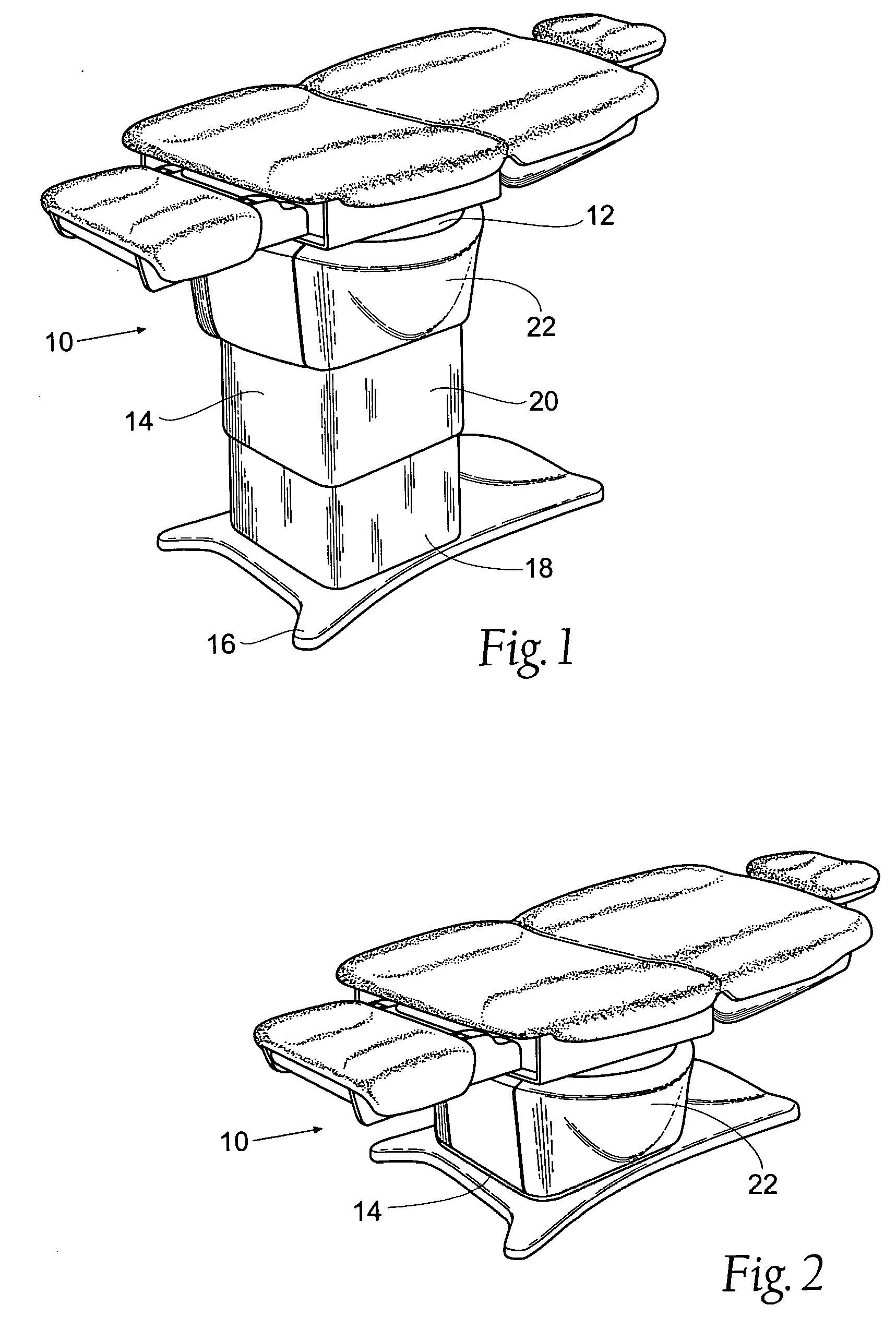
[0022]FIG. 1 is a perspective view of an examination table 10. The table generally comprises a support bracket 12, a support column 14, and a base 16. The focus of the present invention is on the support column 14 and the adjustable nature of the column 14. The column 14 generally comprises three sleeve sections or members: a first or lower sleeve section 18, a second or middle sleeve section 20, and a third or upper sleeve section 22. The first sleeve section 18 is attached to the base 16, the second sleeve section 20 is attached to the first sleeve section 18 and the third sleeve section 22, an...


PUM


Abstract

An adjustable height support column for an examination table / chair is disclosed. The column includes nesting sleeve sections that are relatively slidable with respect to one another. The column uses camming guide rails in combination with cam followers located on the sleeve sections to provide for a column that is sturdy, compact, and may support a sufficiently heavy patient. One or more linear actuators provide for extension and retraction of the column.

Description

BACKGROUND OF THE INVENTION [0001] The present invention relates to medical examination tables and, more specifically, to adjustable columns for examination tables. [0002] Adjustable tables have been previously used in the medical fields. Generally, the focus of prior table adjustment has been for angular or rotational displacement of the table bed. That is, the table base remains stationary while mechanical or hydraulic means tilt or angle the bed in other directions. Though these designs assist an examiner in repositioning a patient for different procedures, they do not allow for vertical mobility of the table. For instance, if a patient were to be moved from a wheelchair or a low resting gurney, such table would still need the patient to be lifted onto the table. [0003] Previous inventions have contemplated adjustable bases. For instance, Schnelle et al. (U.S. Pat. No. 4,589,642), discloses an adjustable base that uses hydraulic cylinders moving in opposite directions to adjust t...

Claims


Application Information

Patent Timeline
IPC IPC(8): A47B9/00
CPCA47B9/20A47B9/00
Inventor DEBRAAL, JACK A.HOFT, MICHAEL F.
Owner BREWER COMPANY LLC THE
Features
  • Generate Ideas
  • Intellectual Property
  • Life Sciences
  • Materials
  • Tech Scout
  • Unparalleled Data Quality
  • Higher Quality Content
  • 60% Fewer Hallucinations
Learn More