Air gun

Inactive Publication Date: 2005-03-31
LAI BAO SHYAN +1
View PDF7 Cites 21 Cited by
  • Summary
  • Abstract
  • Description
  • Claims
  • Application Information

AI Technical Summary

Benefits of technology

[0006] It is therefore a primary object of the present invention to provide an improved air gun including a main body. A striker rod for striking paint bullet and a gunlock for controlling the striker rod are longitudinally arranged in the main body in parallel to each other. The striker rod and the gunlock are driven by a rear block. The rear block is pushed by a thruster disposed in the main body. A controlling valve is disposed at front end of the main body for controlling direction of airflow. The controlling valve is connected with several pipelines for connecting with an air source and the thruster. A trigger is arranged under the bottom of the main body for controlling the direction of airflow of the controlling valve and the strike

Problems solved by technology

This will lead to wear of the striker rod 61 which quickly reciprocally move.
This will also affect the airtight effect between the chamber and the striker rod 61 and lead to i

Method used


Image

  • Air gun
  • Air gun
  • Air gun

Examples


second embodiment

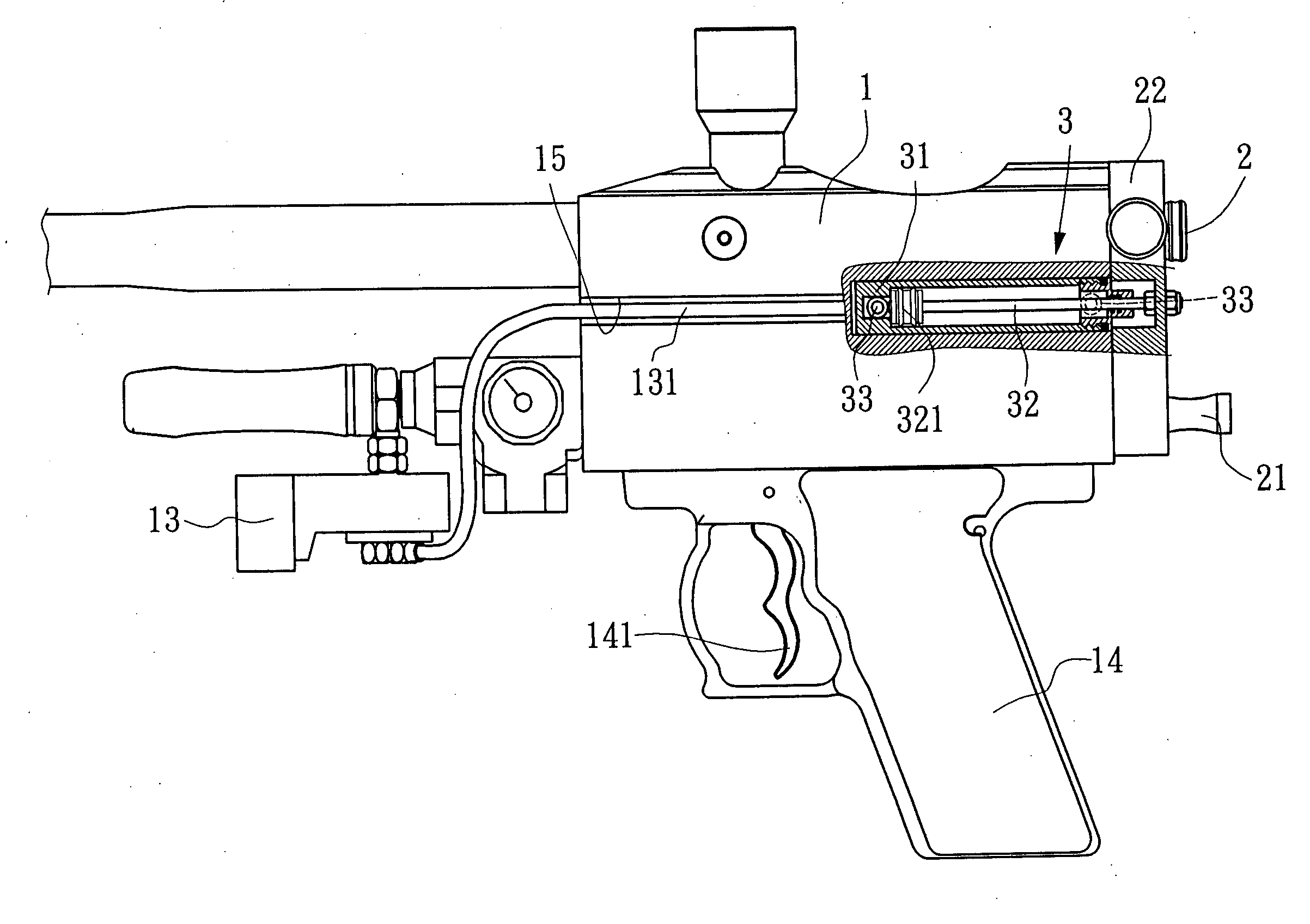
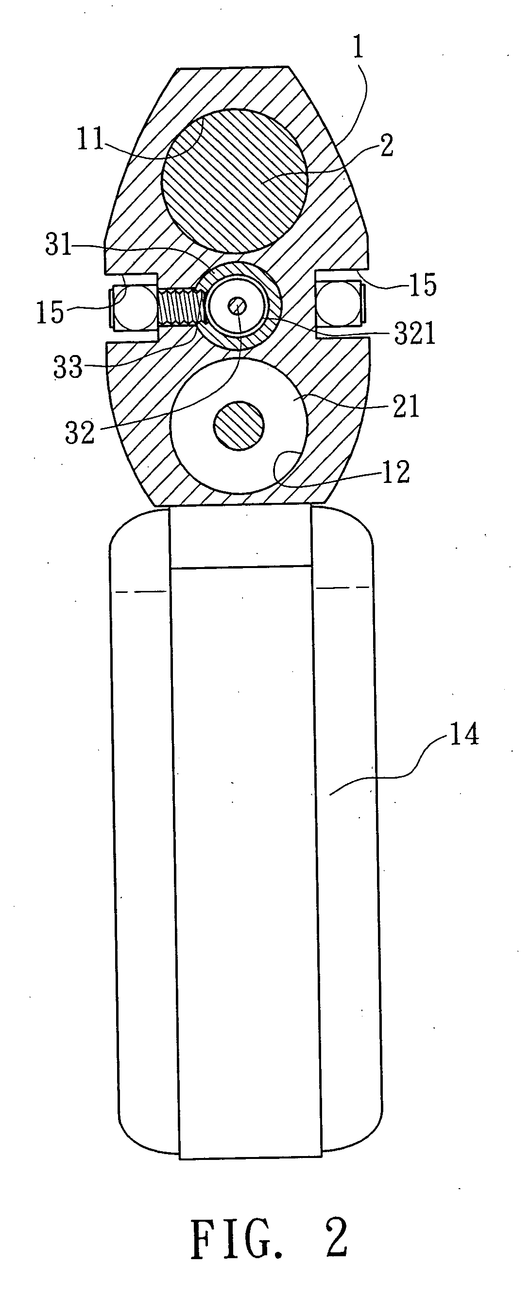
[0025]FIG. 6 shows the present invention, in which the thruster 3 has an air chamber 34 directly formed in the main body 1 right in alignment with the center of the rear block 22. The thruster 3 includes a piston rod 32 disposed in the air chamber 34. The air chamber 34 is positioned between the upper and lower air chambers 11, 12 of the main body 1. One end of the piston rod 32 positioned in the air chamber 34 has a piston 321. The other end of the piston rod 32 extending out of the air chamber 34 is right fixedly connected with the center of the rear block 22. Two ends of the air chamber 34 are respectively formed with two vents 33 for connecting with the pipelines 131 of the controlling valve 13.

first embodiment

[0026] The air chamber 34 is directly formed in the main body 1 instead of the cylinder 31. This can achieve the same effect as the first embodiment and the components of the air gun are simplified.

third embodiment

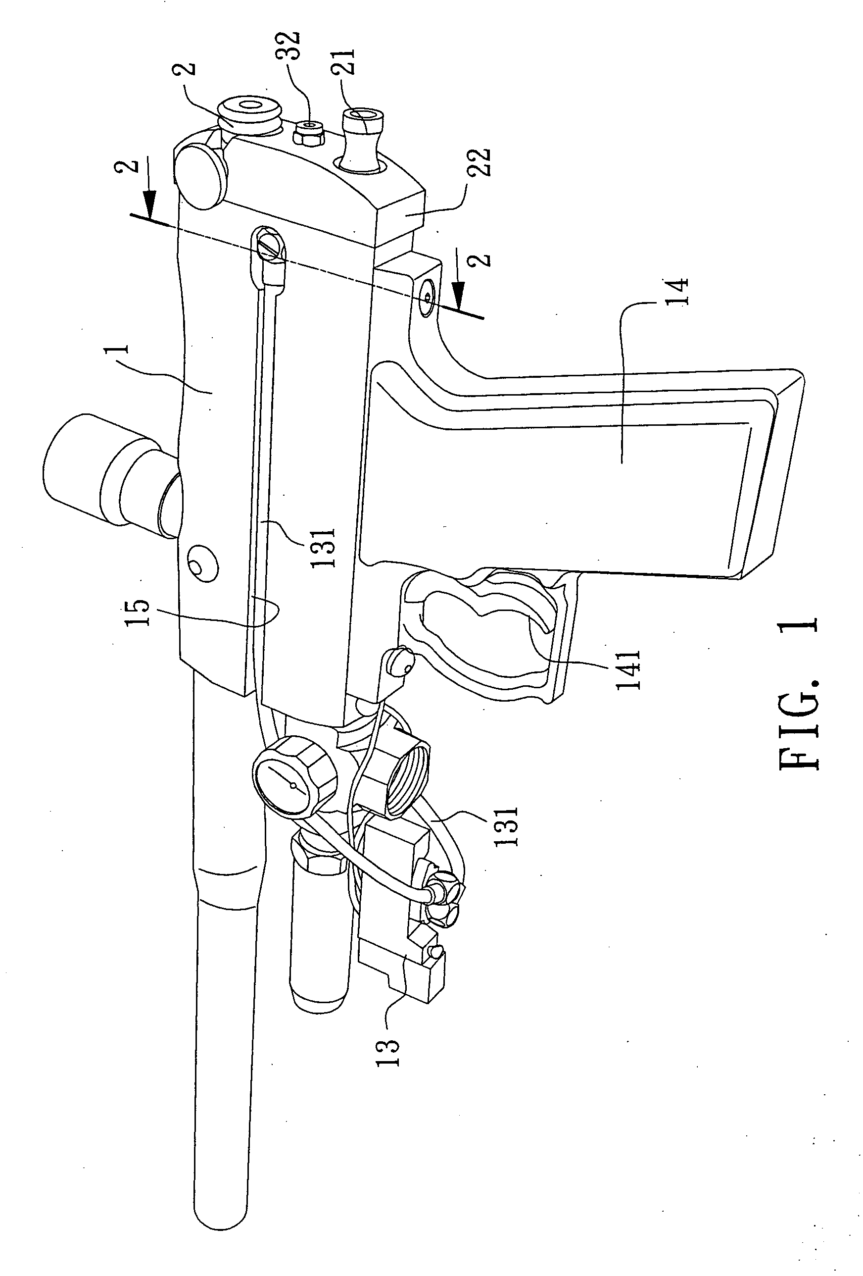
[0027] In the above embodiments, the pipelines 131 of the controlling valve 13 extend along the channels 15 of two sides of the main body 1 to connect with the vents 33 of the thruster 3. Alternatively, two passages 16 can be directly formed in the main body 1 as shown in FIG. 7 which shows the present invention. One end of each passage 16 is connected with the vent 33, while the other end of the passage 16 is connected with the pipeline 131 of the controlling valve 13. Accordingly, the air can be also conducted into the thruster 3 for driving the piston rod 32. Furthermore, the passages 16 are hidden in the main body 1 so that the appearance of the main body 1 is beautified.


PUM


Abstract

An air gun includes a main body in which a striker rod for striking and a gunlock for controlling the striker rod are arranged. The striker rod and the gunlock are driven by a rear block. The rear block is pushed by a thruster disposed in the main body. A controlling valve is disposed at front end of the main body. A trigger is arranged under the bottom of the main body for controlling the direction of airflow and the strike of the gunlock. The thruster is mounted in the main body right at the center of the rear block. The thruster includes a piston rod that is controlled by the controlling valve and axially movable out of the main body. One end of the piston rod extending out of the main body is right fixedly connected with the center of the rear block.

Description

BACKGROUND OF THE INVENTION [0001] The present invention is related to an improved air gun, and more particularly to an air gun in which the piston rod pushes the right center of the rear block. [0002]FIG. 8 shows an air paint bullet gun having a gun body 6 and a gun handle 7. A striker rod 61 for striking a paint bullet and a gunlock 62 are arranged in the gun body 6. A rear block 63 is disposed at rear end of the gun body 6 for driving the striker rod 61 and the gunlock 62. A barrel 65 is connected with front end of the gun body 6 and communicated with the striker rod 61. A cylinder 64 is mounted on one side of the barrel 65. A piston rod 641 is disposed in the cylinder 64 and connected with a link 642. One end of the link 642 extends along one side of the gun body 6 to connect with the rear block 63 for pushing the same. A trigger 71 is mounted on the gun handle 7. The trigger 71 serves to drive a three-position valve 72 for changing the direction of airflow to operate the piston...

Claims


Application Information

Patent Timeline
IPC IPC(8): F41B11/62
CPCF41B11/62F41B11/57F41B11/71
Inventor LAI, BAO SHYANSPURLOCK, MICHAEL STEVEN
Owner LAI BAO SHYAN
Why Eureka
Try Eureka