Paper feeder and an image forming apparatus equipped with the same
- Summary
- Abstract
- Description
- Claims
- Application Information
AI Technical Summary
Benefits of technology
Problems solved by technology
Method used
Image

Examples
embodiment 1
[0047] [Embodiment 1]
[0048] A first embodiment of a paper feeder of the present invention will be described with reference to the drawings:
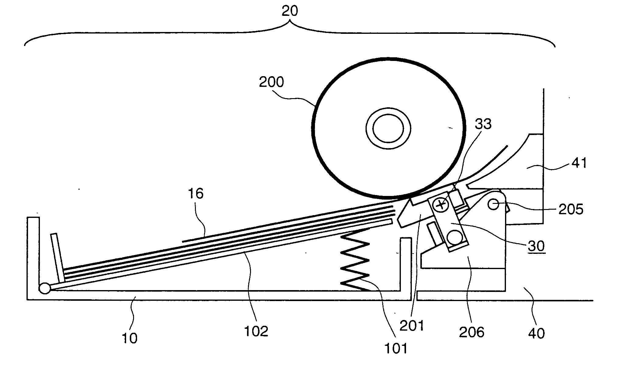
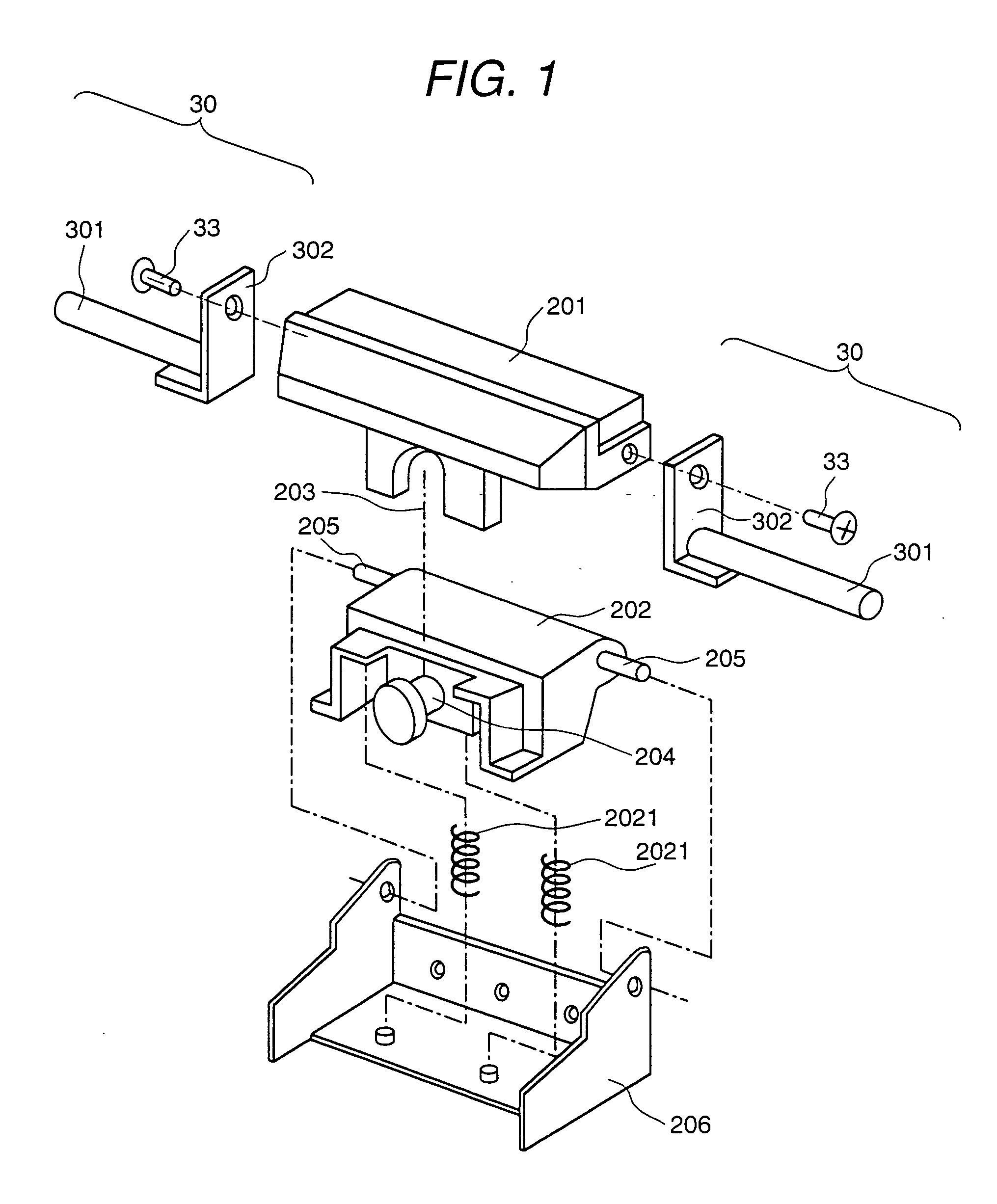
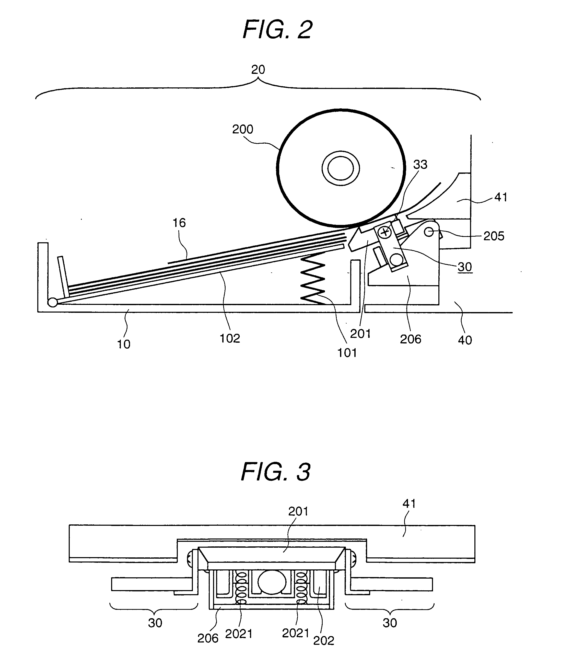
[0049]FIG. 1 is a developed perspective view representing the configuration a paper feeder according to the present invention. FIG. 2 is a diagram representing the configuration of a paper feeder according to the present invention as observed from the side of the printer 1. FIG. 3 is a plan view representing the configuration of a paper feeder according to the present invention as observed from the front of the printer 1.
[0050] The shaft 204 of the separation holder 202 is inserted into the groove 203 in such a manner that the separation pad 201 is supported rotatably about the shaft 204.
[0051] The separation holder 202 is provided with a rotary shaft 205. The rotary shaft is supported by the holder support 206 to permit free rotation of the separation holder 202 about the rotary shaft 205. A pair of coil springs 2021 is installed between the ...
embodiment 2
[0060] [Embodiment 2]
[0061] FIGS. 5(a) and 5(b) show the buffer 30B in a second embodiment of a paper feeder according to the present invention.
[0062] The configuration of this second embodiment of a paper feeder according to the present invention is approximately the same as that of the first embodiment, except for the portion of the buffer 30, and therefore, details of the common elements will not be described.
[0063] The difference between the buffer 30B and the buffer 30A of the first embodiment is that a crimping portion 303A is provided for securing one end of the viscoelastic body 301 to the fixture 303. The other end is a free end without being secured to any place. In this case, the viscoelastic body 301 and fixture 303 are selected in such a way that the buffers 30B will meet the requirement of the primary resonant frequency F and logarithmic decrement δ, as in the case of the first embodiment of the present invention. The buffer 30B based thereon is mounted on each side ...
embodiment 3
[0065] [Embodiment 3]
[0066] FIGS. 6(a) and 6(b) show a buffer 30C in a third embodiment of a paper feeder according to the present invention. The difference between the configuration of the third embodiment of the present invention and the first embodiment is found in the buffer.
[0067] The buffer 30C of the present embodiment differs from the buffer 30A of the first embodiment in that a coil spring 301B is used in the viscoelastic body 301 supporting the separation pad 201, and the surface is coated with a silicone rubber 301C. It is installed in the form of a cantilever beam as in the case of the previous embodiment.
[0068] Similar to the case of the first embodiment of the present invention, the buffer 30C is configured to ensure that the primary resonant frequency F and logarithmic decrement δ of the buffers 30 meets the requirement of the relationship δ / F≧1.75×10⁻² (unit: 1 Hz). This buffer 30C is mounted on each end of the separation pad 201 in a symmetrical form so that a sti...
PUM
 Abstract
Description
Claims
Application Information
 - R&D
- Intellectual Property
- Life Sciences
- Materials
- Tech Scout
- Unparalleled Data Quality
- Higher Quality Content
- 60% Fewer Hallucinations
Browse by: Latest US Patents, China's latest patents, Technical Efficacy Thesaurus, Application Domain, Technology Topic, Popular Technical Reports.
© 2025 PatSnap. All rights reserved.Legal|Privacy policy|Modern Slavery Act Transparency Statement|Sitemap|About US| Contact US: help@patsnap.com