
Method and apparatus for an adjustable trailer

a technology of adjustable trailers and sarvelas, which is applied in the directions of loading/unloading vehicle arrangment, transportation items, transportation and packaging, etc., can solve the problems of high cost, inability to quickly and easily apply the anchoring means disclosed by moller, and the disadvantageous location of the retractable members disclosed by sarvela, so as to reduce the dynamic force

Active Publication Date: 2005-03-31
FOUR DEGREE TRAILER CO
View PDF36 Cites 33 Cited by
  • Summary
  • Abstract
  • Description
  • Claims
  • Application Information

AI Technical Summary

Benefits of technology

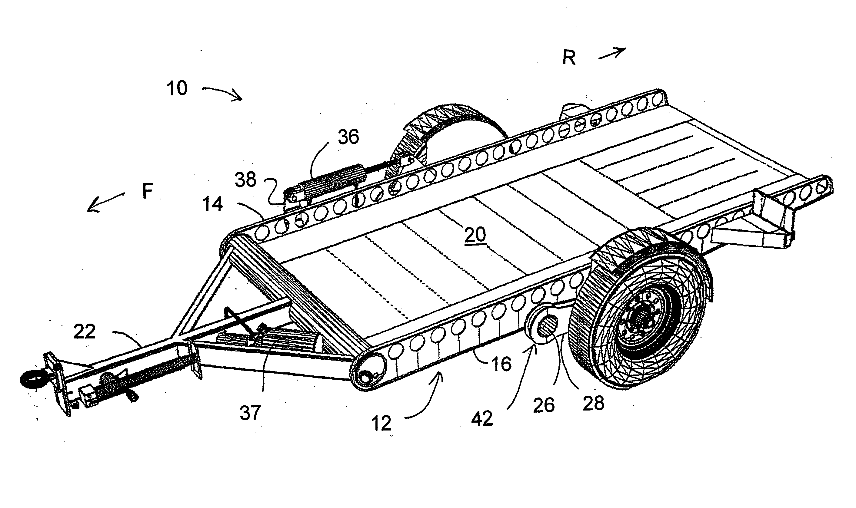
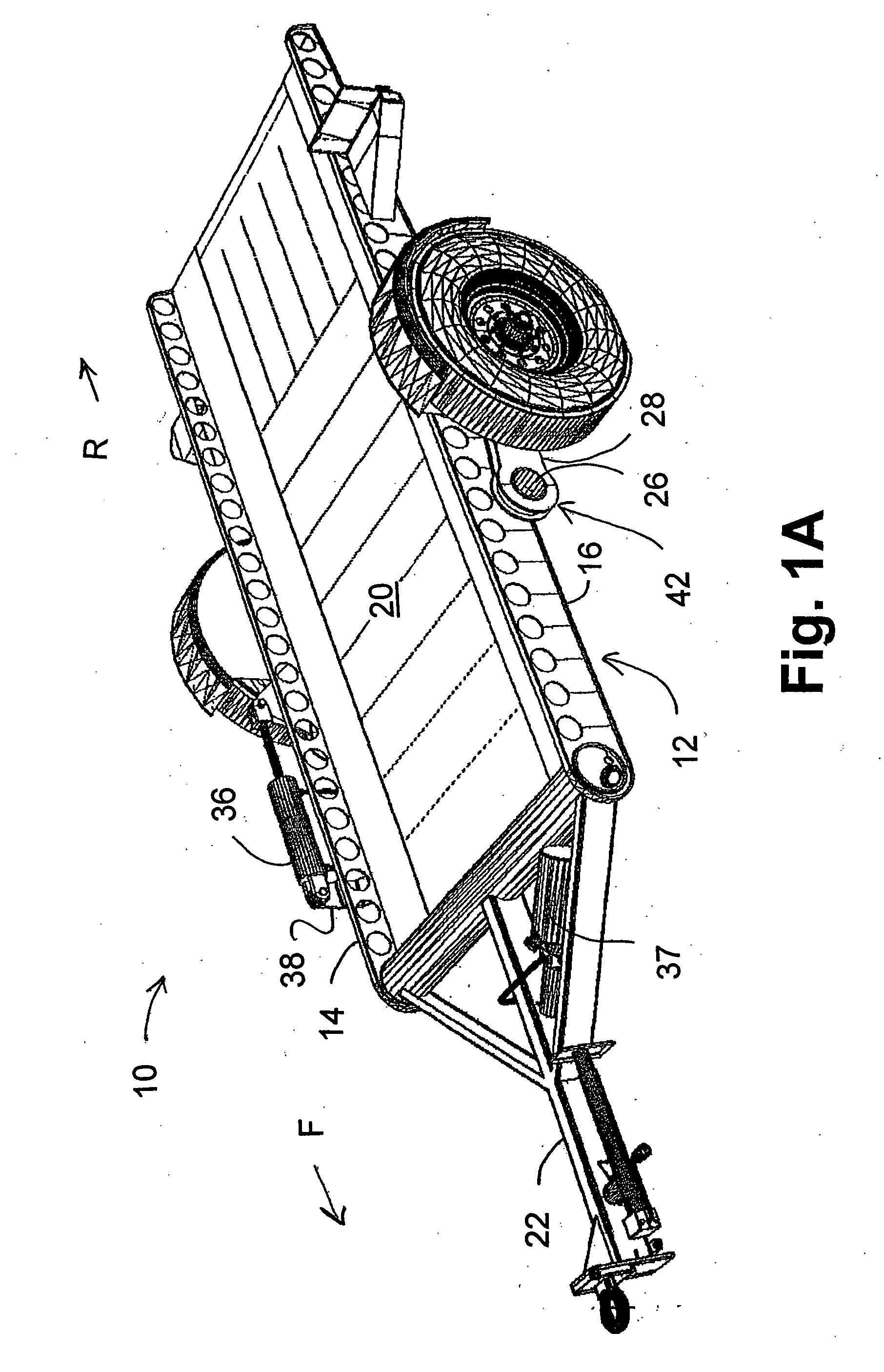
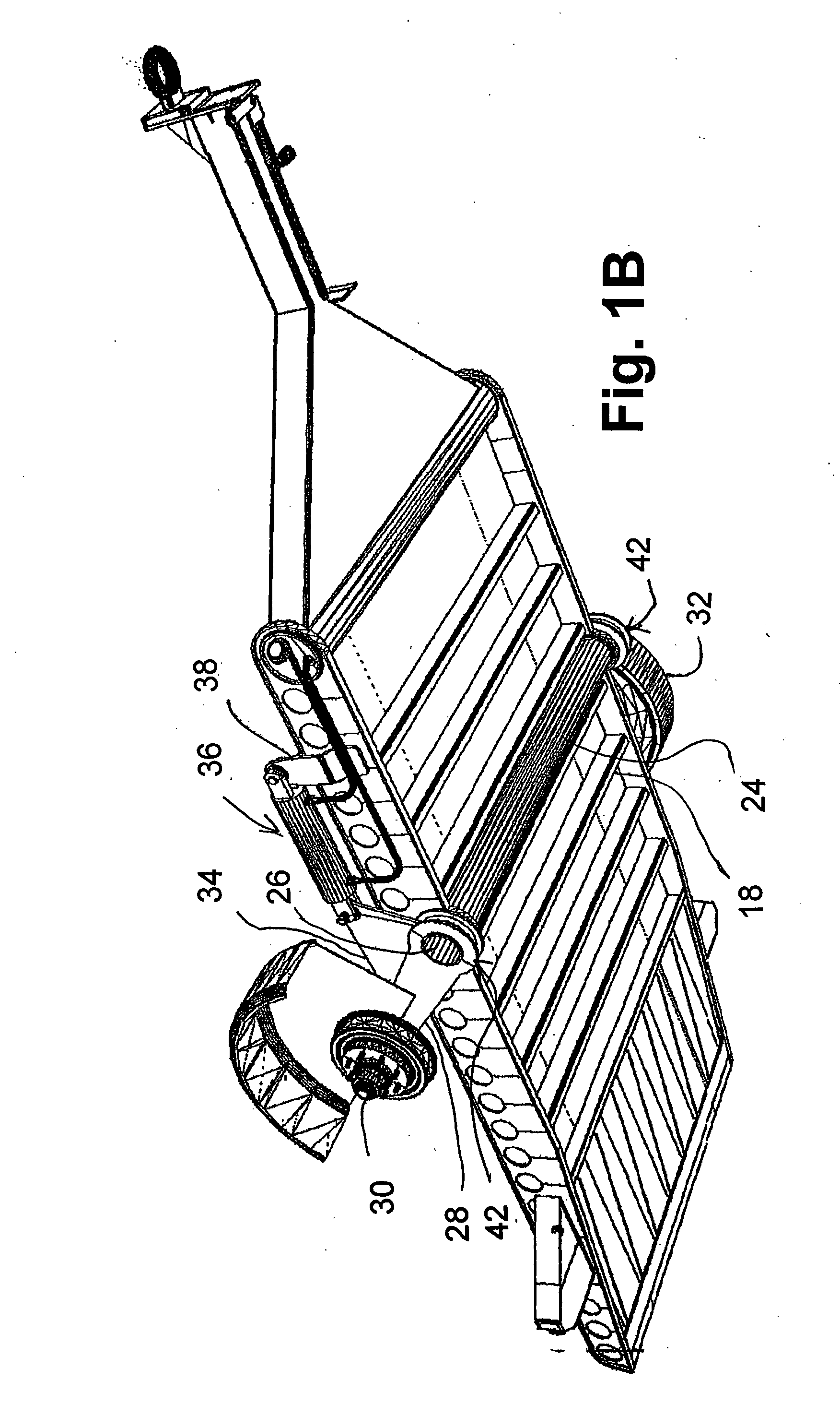
[0012] It is in view of the above problems that the present invention was developed. The invention is an inclining trailer having a front and a rear. The trailer includes a frame constructed to receive a bed and a hitch attached to the frame at the front of the trailer. A tube is pivotally connected to the frame between the front and the rear of the trailer. Left and right wheel support arms are connected to the tube. Each wheel support arm has an axle and a wheel located at its distal end. The trailer further includes means for rotating the tube and a shoe for ground engagement. The shoe engages the ground thereby providing a mid-trailer load bearing point that reduces the dynamic forces to which the trailer is subjected. The shoe is located below the trailer frame and longitudinally between the wheels and the front of the trailer.

Problems solved by technology

However, there has long been a problem in loading a utility trailer.
However, the anchoring means disclosed by Moller cannot be applied quickly or easily.
The retractable members disclosed by Sarvela are hydraulically operated and, thus, expensive.
Further, the retractable members are at a disadvantageous location.
Hence, the trailer has a very limited amount of adjustment.

Method used


Image

  • Method and apparatus for an adjustable trailer
  • Method and apparatus for an adjustable trailer
  • Method and apparatus for an adjustable trailer

Examples


Embodiment Construction

[0036] Referring to the accompanying drawings in which like reference numbers indicate like elements, FIGS. 1A-1C illustrate an inclining trailer 10 having a front F and a rear R. The inclining trailer has a frame 12. The frame 12 includes a first side member 14, a second side member 16, and cross-members 18. The frame 12 is constructed to receive a bed 20. A hitch 22 is attached to the frame 12 at the front F of the trailer 10. While in the depicted embodiment the hitch 22 is a tongue-type hitch, those skilled in the art will understand that the hitch 22 could also be a gooseneck-type hitch.

[0037] A tube 24 is pivotally attached to the frame 12. While in the depicted embodiment the tube 24 is a tube having an inner diameter and an outer diameter, those skilled in the art will understand that the tube 24 is simply a rotating member which could be replaced by a solid member having only an outer diameter, such as a pin. The tube 24 has ends 26. A wheel support arm 28 is operatively c...


PUM


Abstract

A trailer having a front and a rear. The trailer includes a frame constructed to receive a bed and a hitch attached to the frame at the front of the trailer. A tube is pivotally connected to the frame between the front and the rear of the trailer. First and second support arms are connected to the tube. Each wheel support arm has an axle and a wheel located at its distal end. The trailer further includes means for rotating the tube. In one embodiment, the trailer has an inclining feature and a shoe for ground engagement. The shoe is located vertically below a central axis of the tube and longitudinally between the wheels and the front of the trailer. In a second embodiment, the trailer has an inclining and elevating feature. In this second embodiment, the hitch is pivotally connected to the front of the trailer and there is provided means for rotating the tube and rotating the hitch relative to one another to elevate, incline, or decline the bed.

Description

CROSS-REFERENCE TO RELATED APPLICATIONS [0001] None. STATEMENT REGARDING FEDERALLY SPONSORED RESEARCH OR DEVELOPMENT [0002] Not Applicable. APPENDIX [0003] Not Applicable. BACKGROUND OF THE INVENTION [0004] 1. Field of the Invention [0005] This invention relates generally to utility trailers and, more particularly, to an inclining and / or elevating trailer. [0006] 2. Related Art [0007] The utility of a transport trailer is well known. However, there has long been a problem in loading a utility trailer. Often times one would prefer to have a trailer low to the ground for easy loading but raised significantly above the ground for highway transportation. Moreover, there has been a long felt need for a utility trailer that is capable of inclining and / or declining. The functionality of inclining and / or declining allows for loading or unloading of the trailer. [0008] U.S. Pat. No. 3,180,510 to Mollar discloses a trailer for hauling a golf buggy. The trailer raises and lowers for loading an...

Claims


Application Information

Patent Timeline
IPC IPC(8): B60G17/00B60P1/02
CPCB60G2300/04B60P1/027B60G2300/38
Inventor SMITH, WILLIAM M.
Owner FOUR DEGREE TRAILER CO
Learn More