
Inflatable lap belt safety bag

Active Publication Date: 2005-03-31
AM SAFE
View PDF2 Cites 14 Cited by
  • Summary
  • Abstract
  • Description
  • Claims
  • Application Information

AI Technical Summary

Benefits of technology

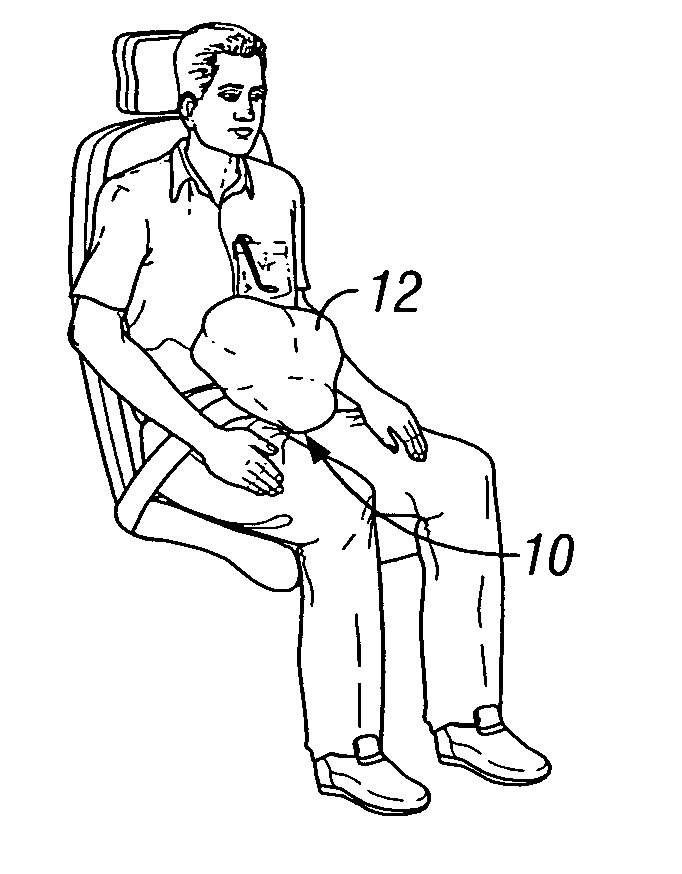
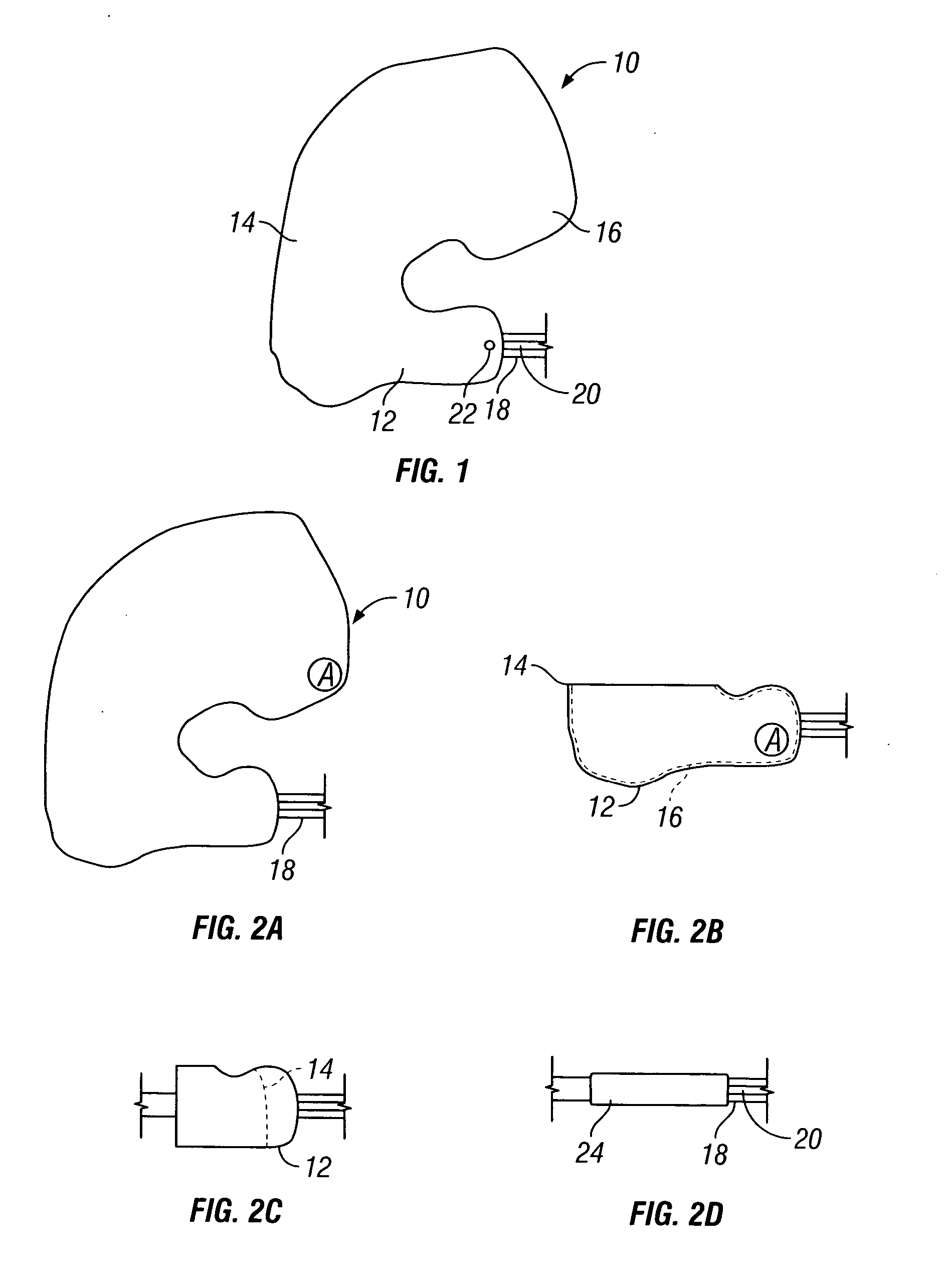
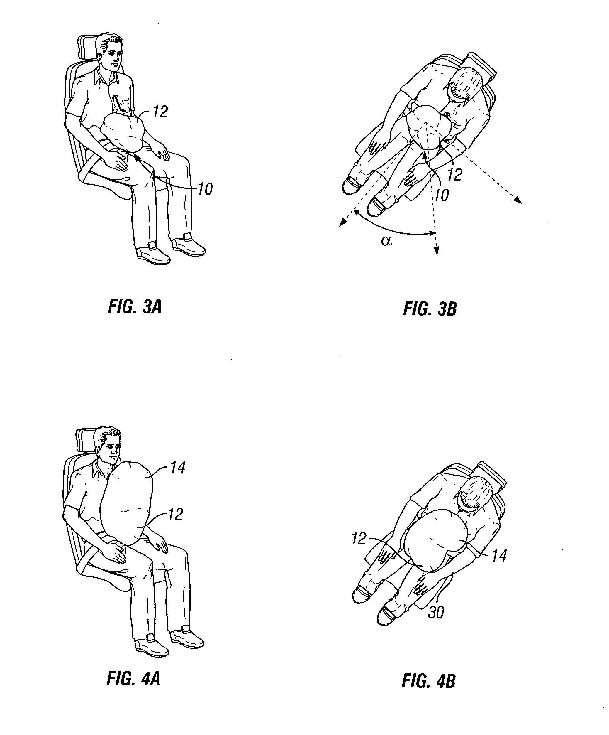
[0007] To overcome the disadvantages of the prior art, a unique lap belt safety bag is provided. The safety bag according to preferred embodiments of the present invention is characterized in that it comprises a lower portion secured to a lap belt proximate an inflation source, a middle section and an upper section. According to the invention, the unique folding sequence of the air bag into the lap belt housing coupled with the shape of the air bag provides a controlled inflation sequence which will inflate the air bag in such a manner as to provide side impact protection or a combination of side / frontal protection, such as a 45° angled seat. According to the preferred embodiments, the upper section is folded into the middle section and the middle section and upper section are folded into the lower section. When the bag inflates, the lower section first inflates to one side away from the inflation source, the middle section next inflates at approximately a right angle to the lower section, and the upper section inflates last back towards the inflation source. Upon inflation, the bag assumes approximately a “C-shape.” It should be understood that by “C-shape,” both a forward “C” and a backwards “C” are meant, as either shape will be assumed depending upon whether the bag inflates to the left or to the right. A primary advantage of this “C”-shape over the other prior art is that this shape greatly simplifies the deployment of the lap-belt mounted airbag in a 45° or 90° side-impact scenario, where the occupant's arm would otherwise interfere with the deploying air bag action. The “C”-shape air bag design avoids this problem.

Problems solved by technology

However, there are disadvantages to the known systems.
The typical single chamber air bag that inflates all at once directly in front of the user does not adequately protect against side impact events.
Although side air bags are available, a mounting system for such air bags may not be available.

Method used


Image

  • Inflatable lap belt safety bag
  • Inflatable lap belt safety bag
  • Inflatable lap belt safety bag

Examples


Embodiment Construction

[0024] Reference will now be made in detail to the present preferred embodiments of the invention, examples of which are illustrated in the accompanying drawings. For purpose of explanation and illustration, and not limitation, an exemplary embodiment of the invention is shown in FIG. 1 and is designated generally by reference character 10.

[0025]FIG. 1 depicts an inflated air bag 10 according to an embodiment of the invention. The air bag 10 generally includes a lower section 12, a middle section 14 and an upper section 16. The air bag 10 is connected to a lap belt 18, typically via stitching. The air bag 10 is also coupled to an inflation source 22 via tubing 20 from which air enters the air bag, proximate the lower section 12, for inflation of the air bag 10. The tubing 20 is coupled to an air source (not shown) and a circuitry, as known in the art, to detect an impact event in which inflation of the air bag 10 would be desirable. As shown, the air bag 10 has approximately a C sh...


PUM


Abstract

A safety bag comprising a lower portion secured to a lap belt proximate an inflation source, a middle section and an upper section. The upper section is folded into the middle section and the middle section and upper section are folded into the lower section. When the bag inflates, the lower section first inflates to one side away from the inflation source, the middle section next inflates at approximately a right angle to the lower section, and the upper section inflates last back towards the inflation source. Upon inflation, the bag assumes approximately a “C-shape.”

Description

BACKGROUND OF THE INVENTION [0001] 1. Field of the Invention [0002] The present invention relates to an inflatable lap belt safety bag. Particularly, the present invention is directed to an inflatable lap belt safety bag which provides improved safety characteristics. [0003] 2. Description of Related Art [0004] Inflatable safety bags are known in the art. In some applications, these safety bags may be connected to a lap belt and an inflation source thereabout to provide for an inflatable lap belt safety bag. The safety bags are generally operable through electronics which couple an inflation activation system to a deceleration sensor circuitry. Thus, when a deceleration characteristic of an impact event occurs, a signal is sent to the activation system. The activation system activates an inflation source which inflates a bag of air to provide a cushion for the user in the event of an impact. [0005] Such conventional methods and systems generally have been considered satisfactory for...

Claims


Application Information

Patent Timeline
IPC IPC(8): B60R21/16B60R21/18B60R21/237
CPCB60R21/18B60R21/237B60R21/231
Inventor KEESLAR, KEVIN J.FOUBERT, DANIEL NICK
Owner AM SAFE
Learn More