Technique for compensating undesired effects in optical links of an optical communication network

Inactive Publication Date: 2010-05-27
ECE TELECOM LTD
View PDF16 Cites 6 Cited by
  • Summary
  • Abstract
  • Description
  • Claims
  • Application Information

AI Technical Summary

Benefits of technology

[0037]providing one or more of said adjustment modules at each node of the optical network section, for serving one or more respective optical links incoming a

Problems solved by technology

Surprisingly, none of the prior art sources solves a long felt and complex problem known for optical networks, which is as follows: both when designing an optical network, and when maintaining proper functionality of the network, specialists must take care of each specific link/node of the network separately by considering length of each incoming optical link, power attenuation of the optical signal arriving via that link, chromatic dispersion of

Method used


Image

  • Technique for compensating undesired effects in optical links of an optical communication network
  • Technique for compensating undesired effects in optical links of an optical communication network
  • Technique for compensating undesired effects in optical links of an optical communication network

Examples


Example

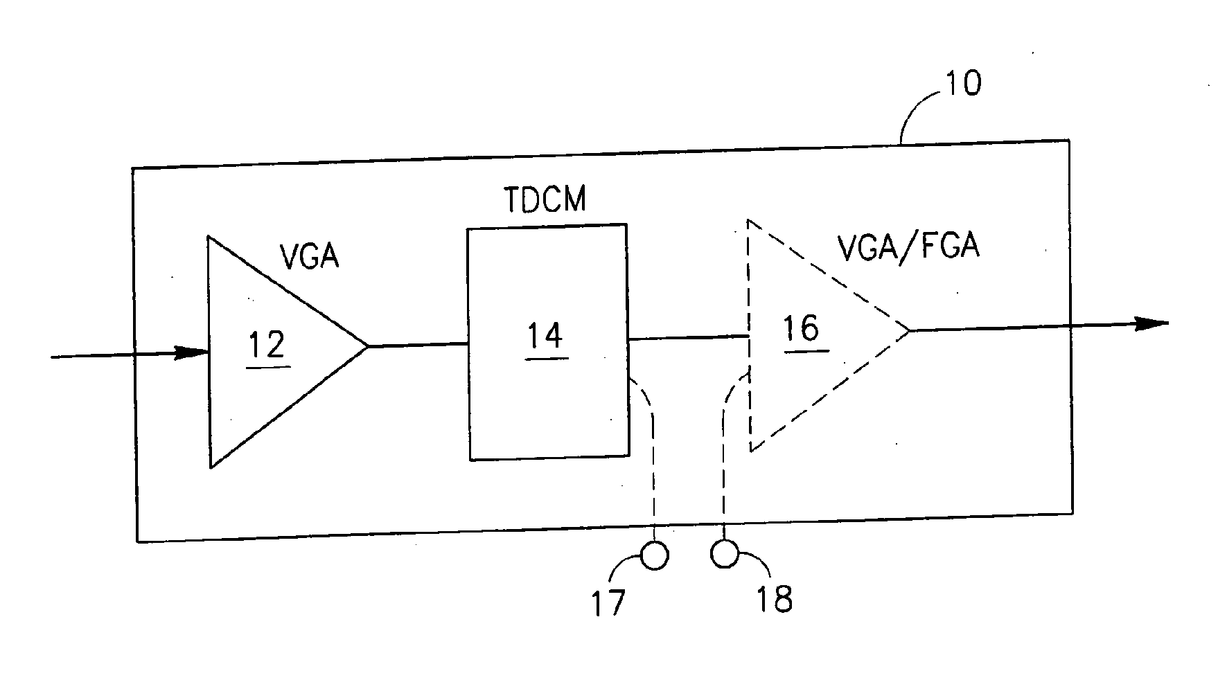
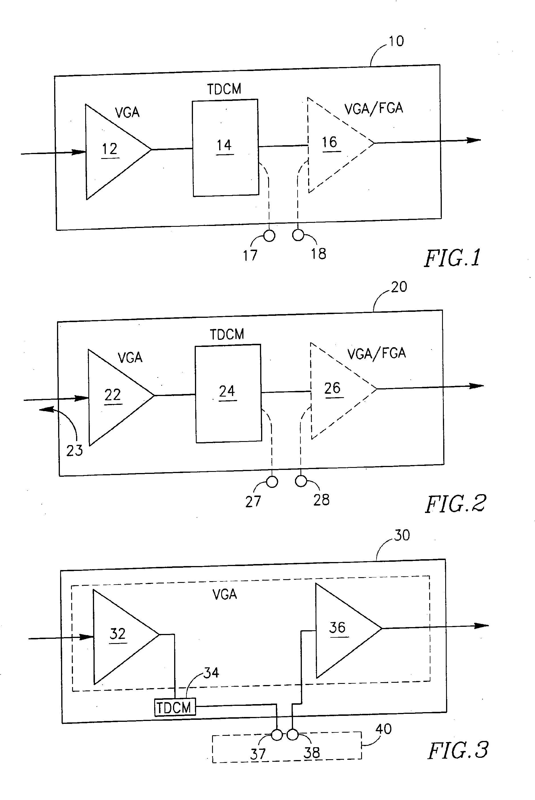
[0054]FIG. 1 shows a basic embodiment of the proposed ready-made adjustment module 10 for optical communication links, comprising a variable gain amplifier VGA 12 and a tunable dispersion compensation module TDCM 14 connected in a chain. Optionally and preferably, the adjustment module 10 comprises a second, additional amplifier 16 in the chain, which may be either a variable gain amplifier VDA or a fixed gain amplifier FGA. The figure further shows that, in case module 10 comprises the two amplifiers 12 and 16, the module may further be provided with two external contacts 17 and 18 to enable the insertion of a functional element into the chain between the amplifiers 12 and 16. These amplifiers may be two separate erbium doped fiber amplifiers—EDFAs. Alternatively, amplifiers 12 and 16 may constitute two stages of a double-stage optical amplifier, provided with contacts 17 and 18 in the mid-stage (see FIG. 3).

[0055]It should be noted that, within the adjustment module 10, the tunabl...


PUM


Abstract

A technique for compensating undesired effects in optical links of an optical communication network, using adjustment modules suitable for inserting into optical links, preferably into the links incoming network nodes. Each of the adjustment modules serves for compensating two or more different physical effects accumulated in the optical link when transmitting an optical signal there-along. The module comprises at least two controllable blocks respectively comprising a variable gain optical amplifier VGA for selectively compensating power loss and a tunable dispersion compensation module TDCM for selectively compensating chromatic dispersion.

Description

FIELD OF THE INVENTION[0001]The present invention relates to the field of designing, deploying and exploiting optical communication networks, more particularly to a technique for handling non-uniform individual characteristics of various transmission links or sections in optical communication networks.BACKGROUND OF THE INVENTION[0002]The maximum distances optical signals can travel through an optical fiber before degrading to the point of being undetectable by a receiver is limited, among other things, by power loss due to attenuation introduced by the fiber and other components and by signal distortion due to chromatic dispersion, fiber nonlinearity and polarization mode dispersion (PMD).[0003]The power loss due to the fiber and components' attenuation may be overcome by employing optical amplifiers that amplify the propagating signal, thus restoring its power. Transmission systems may include a series of optical amplifiers, usually erbium-doped fiber amplifiers (EDFAs), periodical...

Claims


Application Information

Patent Timeline
IPC IPC(8): H04B10/18H04B10/17H04B10/2513H04B10/294
CPCH04B10/294H04B10/2513
Inventor LICHTMAN, EYAL
Owner ECE TELECOM LTD
Why Eureka
Try Eureka